
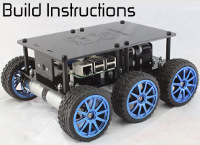
Pin layout for Thunderborg motor driver
Forums:
Hi,
I would like to connect a compass (CMPS14) to my Monsterborg robot's Pi, ideally via I2C or else serially. As the Thunderborg motor controller also powers the Pi, can you please share the male/female layout for the 6 connections of the Monsterborg.
Thanks!
-
- Log in to post comments

piborg
Wed, 03/29/2023 - 09:40
Permalink
ThunderBorg 6-pin connections
danesh
Wed, 03/29/2023 - 13:09
Permalink
Thank you.
Thank you.
danesh
Sun, 04/02/2023 - 08:30
Permalink
Powering PI with Thunderborg
Hi,
To test if the motor controller was being detected on I2C, I plugged my motor controller to the PI, across all six pins, and now my PI does not boot -- the chip just gets hot but no LEDs flash. The motor controller was the lid variant with a 12V ~2400 mAh 10 AA battery pack. No motors were connected to it. Am not sure what I did wrong. Any ideas?
Also, can you please advise if I need to connect all six pins to the Pi. If I just connect one of the 5V pins, GND, SCL and SDA, would that do?
And, can the daisy chained pins (green and yellow outlined blocks in your above diagram) be used to power the CMPS14 (needs 3.3-5V), and connect it on the same I2C bus with the daisy chained SCL and SDA pins.
Thanks again!
piborg
Mon, 04/03/2023 - 12:05
Permalink
It sounds like 5V may have been connected to the wrong pin
It sounds like you might have accidently connected 5V to one of the other pins on the GPIO header. The Raspberry Pi is not designed to tolerate more than 3.3V on general GPIO pins, and getting 5V, 3V3 or GND mixed up would also be bad. In either case this may have caused permanent damage to the Pi.
I have copied the ThunderBorg cable connections section from the getting started page at the bottom of this post for further clarification.
For the ThunderBorg to work it needs at least one 5V along with the 3V3, GND, SCL and SDA connected to work, five cables in total. The 3V3 line powers some of the logic on the ThunderBorg and provides the reference high level for the I2C lines.
Yes, you should be able to connect other I2C devices to the daisy-chain connector and have them share the bus. For the CMPS14 you want to make sure you have it connected in I2C mode, NOT serial mode.
It is not clear from the CMPS14 datasheet, but you may have to power it from the 3V3 pin to ensure that it is compatible with the 3.3V I2C levels used by the Pi. CMPS14 datasheet.
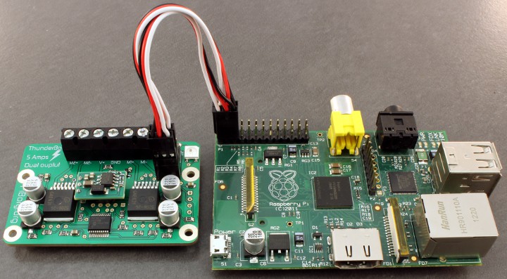
Using cables to the Pi (optional)
If you are using cables instead of mounting the ThunderBorg you will need to connect the two provided 3-pin cables from the first six GPIO pins on Raspberry Pi to the six-pin socket on the ThunderBorg:
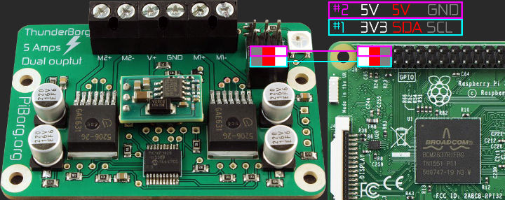
These outlines show an individual 3x1 pin cable (two supplied), the coloured boxes show the colour of the wire (grey is used instead of black in the diagram).
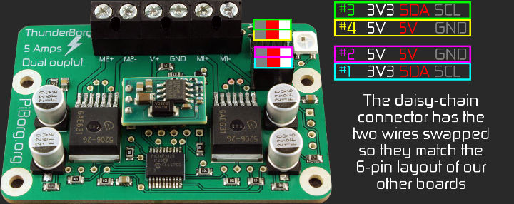
You can also connect additional ThunderBorgs or PiBorg boards by using the six-pin daisy-chain connector, read further down for instructions on configuring the software correctly to run with multiple ThunderBorgs attached.