
Ultraborg/Thunderborg combination power
Forums:
Hi,
Sorry this is probably a really basic question but I'm trying to daisy chain an ultraborg and Thunderborg board to control dc motors, servo motors and ultrasonic sensors and I'm not sure how to sort the power. At the mo I have a 10 AA battery setup with the thunderborg to control the dc motors and raspberry pi. I know the ultraborg will need more power for the servos but wondering whether I can supply this from the 10AA pack. If so, how would I connect this? I read on the instructions for the diddyborg/mearm that this could be done with a battborg but I'm not sure exactly how this setup would look.
Any help would be appreciated!
Thanks
- Log in to post comments
piborg
Thu, 02/15/2018 - 11:44
Permalink
Wiring a BattBorg for the servos
You can use the same 10x AA pack for both the BattBorg powering the servos and the ThunderBorg :)
Probably the easiest way to wire both is to connect the 9V style cable to the V+ and GND on the ThunderBorg and run a red wire between V+ on both boards and GND on both boards. Make sure both cables are gripped well in the ThunderBorg connectors to get a good power connection.
I have made a quick diagram below of the connections required, including which pins on the 6-pin BattBorg header are needed for the 5V and GND to the UltraBorg. Hopefully that will make things a bit clearer.
Remember to double-check the 6-pin connections on the UltraBorg and ThunderBorg when connecting the 3-pin cables to avoid getting the wires swapped.
Click on the image to make it larger :)
EDIT:
The image was wrong, see corrected one further down.
tgbenson
Thu, 02/15/2018 - 19:51
Permalink
Thanks
Thanks so much - the diagram makes it a lot clearer. I'll give it a go and let you know how I get on!
tgbenson
Fri, 02/23/2018 - 19:52
Permalink
Double check
Hmm, so connected things up as shown in the diagram but when turned on there was a degree of smoking which I generally take to be a bad thing. Can I just triple check the battborg connections in the diagram as it looks like the V+ is connected to the other side from other pics I've seen. Should the battery's +ve terminal not be connected to the V+ on the battborg?
piborg
Fri, 02/23/2018 - 22:31
Permalink
Incorrect BattBorg wiring :(
I am really sorry, the BattBorg V+ and GND connections were the wrong way round in my diagram :(
You are quite correct, the V+ for the BattBorg should be connected to the +ve on the battery and the GND for the BattBorg should be connected to the -ve on the battery.
I have attached a fixed copy of the image below and removed the old diagram.
It is fairly likely that this mistake will have damaged your BattBorg. If you send us a message using our contact form with you address we will send you out a replacement.
Hopefully it was just the BattBorg which was smoking.
tgbenson
Wed, 02/28/2018 - 14:30
Permalink
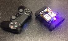
Me again...
Hi, still having some problems I'm afraid. I am now using a working BattBorg and have tried to follow your wiring diagram as carefully as I can (I have attached a photo, apologies for the slightly wonky wire colours). However, now it seems I cannot find either the Thunderborg or Ultraborg on the I2C buses. I have tried both scanning for Ultraborg as in the trouble shooting and scanning for the thunderborg, both say no Ultraborg/Thunderborg found. I have also tried i2cdetect, which does not seem to see anything.
One thing I'm very confused about is why on the diddyborg v2 instructions it seems to want me to connect the the rasp pi to a different 6 pin header (i.e. the female one) to the instructions on the thunderborg getting started page, and your diagram above. I have now tried both to no avail. Is there any chance I could have damaged the thunderborg in the process?
Basically now nothing works where at least the thunderborg worked before. Any help would be very much appreciated!!
piborg
Wed, 02/28/2018 - 20:25
Permalink
Checking the ThunderBorg
Since the LED on the ThunderBorg is still working there is a chance that the board itself is still fine and something else is causing the problem. At this point I would suggest we try and check if the ThunderBorg is working correctly on its own.
Disconnect both of the 3-pin cables between the ThunderBorg and UltraBorg and see if you are able to talk to the ThunderBorg again. If this works then the problem is likely to be either with the UltraBorg or the connections to the UltraBorg.
If you cannot see the ThunderBorg on its own it is possible that the cables are not making good contact. The wires you are using are quite short and the SDA / SCL signals need a good solid connection to work correctly. In this case I would suggest you try going back to the original cabling as per the DiddyBorg v2 instructions and see if that gets the ThunderBorg to work again.
Once we know if the ThunderBorg is working and if the cables needed to be changed we can have a better guess as to what is causing the trouble.
On a separate note you still have the 5V link jumper fitted on the UltraBorg. This should be removed when the UltraBorg is powered via the V+ and GND pins.
tgbenson
Mon, 03/05/2018 - 21:16
Permalink
Thanks
Thanks again for your help. I disconnected the ultraborg and changed to a longer cable as suggested but oddly the thunderborg was still not being recognised. After a few attempts adjusting cabling I ended up just trying a different pi, which immediately recognised both boards. Slightly unsatisfying as I'm not sure what the issue was but all seems to be working fine now!
tgbenson
Mon, 03/12/2018 - 15:33
Permalink
Servo control
Hi, I'm now trying to get my servo motors to work on the ultraborg but am getting no response whatsoever. The ultrasonics are working ok. You know you mentioned I should have disconnected the jumper, is there any chance I've damaged something by not doing this initially and powering the ultraborg through the battborg. I have looked at the troubleshooting for the ultraborg and can't see much on an unresponsive servo beyond double checking the connection and running Init(). There are no errors when I do this, and I have triple checked the servo wiring.
piborg
Mon, 03/12/2018 - 18:43
Permalink
Servos not working
It is possible, but there are a couple of other things it might be.
The first thing to do is just try each servo on its own to see if it is okay. We have seen a bad servo upset all of the outputs on rare occasion. In this case removing the problem servo should allow the others to work.
The second thing to try is the tuning GUI. This will allow a larger movement range and bypasses the limit checking. If you can get the servos to move using the tuning GUI you should be able to set the servo up so that the standard GUI works properly.
deleolubodun
Sun, 10/21/2018 - 23:16
Permalink
using ultrasonic sensors to drive the motors using ThunderBorg
How can I use the result from an ultrasonic sensor (with UltraBorg) to drive the motors using ThunderBorg
piborg
Mon, 10/22/2018 - 20:12
Permalink
It depends what you want it to do
It depends what you want it to do, but for a simple example you can modify the
ubServoFromDistances.pyexample to set motor speeds on the ThunderBorg instead of servo positions.All you need to do is add the usual import and setup code for the ThunderBorg (like in
tbSequence.py) to the script before the loop.After the setup code add a maximum power calculation like this:
# Power settings
voltageIn = 12.0        # Total battery voltage to the ThunderBorg
voltageOut = 6.0        # Maximum motor voltage

# Setup the power limits
if voltageOut > voltageIn:
    maxPower = 1.0
else:
    maxPower = voltageOut / float(voltageIn)
but with the correct voltages for your batteries and motor.
To set the motor speeds simply change these two lines:
for these instead:
Now the reading from sensor #1 should control the speed of motor 1 and sensor #2 should control the speed of motor 2.
The speeds will vary by the distance: