
How does diablo distributes power to motors?
Forums:
I want to know how does the diablos power distrubution goes with multiple motors and diablos. So if I have 4x Dc motors of 24V and 500W. Can one diablo give 50A of power at 24v to each motor or does it split the power between the two? If so do I have to buy 4 diablos and run each motor on separate diablo to get full power from the motors?
- Log in to post comments

piborg
Fri, 09/20/2019 - 10:15
Permalink
Diablo motor power
The Diablo can put out a maximum of 50A per output. How this is divided up will depend on how the motors are connected.
If only one motor is connected per output it can draw a maximum of 50A to the supply voltage.
If two motors are connected per output in serial they each get a maximum of 50A, but the voltage is split between them.
If two motors are connected per output in parallel they each get the full supply voltage, but the 50A current is split between them.
Also note that to supply 24V @ 50A the output must be connected to a supply which can provide this. If the same supply is connected to both outputs then it would need to handle a full 100A!
Finally the motors you have are not rated for running a continuous 50A at 24V:
however the total stall current for the connected motors to a single output needs to be less than the 55A maximum for the Diablo. This is higher than the normal running current for the motor.
Kullinaattori
Tue, 09/24/2019 - 14:58
Permalink
Thank you for your answer.
Thank you for your answer. But I'am still unsure how it would distribute the power in my case. So I made a litle picture of it. If this would help, make things clearer.
Thank you in advance!
piborg
Wed, 09/25/2019 - 10:31
Permalink
Power evenly divided
In that arrangement all four motors can get the full 24V from the battery at the same time. The current supplied by the battery is evenly divided between them.
Kullinaattori
Wed, 09/25/2019 - 11:28
Permalink
And how are the Amps divided?
And how are the Amps divided? So of I got it right each motor gets max 25A? Or just 12A? Or?
piborg
Wed, 09/25/2019 - 14:13
Permalink
Split evenly between all four motors
The maximum amps (current) available to each motor is evenly split. This will be the maximum amps that the battery can supply divided by 4.
Kullinaattori
Wed, 09/25/2019 - 18:39
Permalink
How did you solve this problem of power with doodleborg?
Thank you for your previous answer, it helped a lot! But can you explain how does your DoodleBorg work? because if I got it right it has 6 * 350W motors and two 12V battery packs. So if the motors are 24V then you would need 14,58A for each motor and in total you need 90A power from batteries. And if it runs on 12V then it would be 29,16A for each individual motor and 175,2A in total. So what kind of batteries are you using? Do normal motorcycle batteries provide enough Amps to make it run?
piborg
Thu, 09/26/2019 - 10:56
Permalink
Motorcycle batteries
Yes, motorcycle and car batteries can supply fairly high currents for a long burst (~30 seconds). This is generally known as "cranking amps".
The ones we are using are similar to this: https://www.tayna.co.uk/motorcycle-batteries/yuasa/yt14b-bs/
The CCA value (cold cranking amps) is 210A for the linked battery, which would be plenty.
Running the motors at a lower voltage will not consume more current, instead the motors will spin slower and have less torque.
Kullinaattori
Thu, 09/26/2019 - 12:39
Permalink
What about AGM?
Awsome! Thanks once again! Do you know about mobility scooter AGM batteries, how they work. I heard that they distribute power differently compared to car or motorcycle batteries. Do you hapen to know how exactly? And what kind of battery would be optimal for my type of configuration? I want to operate the robot for 1h.
piborg
Fri, 09/27/2019 - 12:27
Permalink
Running time
To work out the running time you need to look at the Ah (amp-hours), larger numbers mean the battery can deliver power for longer.
The actual current used by the motors will vary depending on how the robot is driven, hard acceleration will use the most.
As a guideline DoddleBorg uses 10 Ah batteries and we were seeing upto 20 minutes of running time.
Kullinaattori
Wed, 10/30/2019 - 16:53
Permalink
Hi!
Hi!
We have been running some new tests, with new and improved configuration. And we have stumbled upon a under-voltage problem with the diablo boards. The motors run smoothly when they are not loaded. But as soon as we put the robot down and there is some load on the motors and we measure the voltage we don't get the minimum 23.8V volts that are needed to run the motors efficiently. What would be the code for setting the minimum voltage? Or setting the lower drive power? (Note: motors are new and in excellent condition and all wiring is done correctly. Also battery is very powerful and can supply the need power.)
piborg
Wed, 10/30/2019 - 16:43
Permalink
Battery voltage under load
What you are seeing is the batteries voltage dropping when the motors are drawing more current. Put simply a larger load on the motors causes them to draw more current, in turn more current drawn from the battery causes it to deliver a smaller voltage. This is perfectly normal.
The amount of load on the motors will largely depend on the overall weight of the robot. This means a heavier robot or carrying heavy loads will cause a larger drain on the battery. When the motors are not loaded they will put a very low drain on the battery as they have a much easier time turning.
You can reduce the voltage drop by either reducing the weight of the robot or using a battery which can handle a larger current draw (cranking amps). You will always get some voltage drop regardless, especially under acceleration.
Kullinaattori
Wed, 10/30/2019 - 17:03
Permalink
Hi!
Hi!
Well the battery can provide 430A of cranking amps. So I don't think that that is the problem. The stats are following ( if it will help at all) We have 4 * 500w 24V motors. The robot weights now approx. 110kg. It has also 1.8 gear ratio with chains.
I'am thinking of a code that would make Diablo boards provide from the start the required 24V to the motors as soon as I command it to go forward. Would seeing the code help you?
piborg
Thu, 10/31/2019 - 11:18
Permalink
Battery voltage
I think there is a bit of confusion about how the battery works.
Cranking amps are the numbers of amps the battery at 0°C can deliver for 30 seconds and maintain at least 1.2V per cell, which is 14.4V for a 24V battery.
This means your battery would provide a minimum of 14.4V when 430A is being drawn and the battery is fully charged. At lower current draws the voltage drop will be smaller, but there will always be some drop.
I think the big question is how much of a drop you are actually seeing. If you can it would be good to get the battery voltages:
Kullinaattori
Wed, 11/06/2019 - 20:13
Permalink
Insufficient voltage
Hi! Sorry that it took me this long to answer and put some measurements, but I was on a business trip, and now I'am back with some data :). So I did the measurements as you asked and I got the following readings:
1) When battery is connected the voltage from the batteries is 24V at Diablos battery connection points. SO there is no power loss there.
2) When the motors are moving without load the readings starts from 0V and goes up to 18,7V before the motors stall.
3) When there is load the motors manage to get about 5 volts before they stall.
4) With power of 50% I get only 9,8V volts out
5) With 75% power I get 15V out.
With basic calculation: for the motors to work properly the window is 19V absolute minimum and about 27V for maximum (If we don't want to overcharge them)
If I'am getting this correct we should be able to tell the Diablo board to start operating the motor from 20V and up. How exactly do I do that? O r is there something else to do? What I'am missing here?
piborg
Thu, 11/07/2019 - 10:52
Permalink
Battery voltage
I think you have misunderstood what I wanted you to measure.
The measurements I was expecting were:
If I understand you correctly the 24V reading is from test #1, but none of the other readings are from the battery.
Kullinaattori
Thu, 11/07/2019 - 13:00
Permalink
Yes the first one is from the
Yes the first one is from the battery when the motors are not powered.
And the rest is taken from the motor connection points at Diablo.
Can you tell me why this two measurements should be taken from the battery also? If the battery is feeding constant 24v even while the motors are running...
piborg
Thu, 11/07/2019 - 13:53
Permalink
Measuring the battery
The point of measurements 2 and 3 is to measure how much the voltage from the battery is dropping while it is delivering current to the motors.
Kullinaattori
Thu, 11/07/2019 - 17:30
Permalink
I did the measurments and the
I did the measurments and the drips are the following: when unloaded and it uses 50% of power it drops from 23.7V to 21.5V. And I get the same drop when loaded and I use the same power. Well I need to charge the batteries obviously. But still the voltage drop isn't that big.
Kullinaattori
Mon, 11/11/2019 - 16:10
Permalink
Well I charged the batteries
Well I charged the batteries and measured all the things again. So now that it is fully charged it has a charge of 25.6V. When loaded it drops to 23.8V. It is still slugish and powerless. We then tryed to overcharging it and made it 36V system. With same results. The voltage drop is about 2V but the robot just wont move well in any direction. And what is more strange it is that when I try to drive it backwards it will shutdown after a while. I'm not sure anymore what to do... I asked a electrician to check all the wiring on the bot and he said it was done well and corectly. Batteries are AGM motorcycle batteries that shoyld provide enough juice to the system. So what could be the problem? Do you still think that the problem are the batteries? Or could it be something with the code?
Kullinaattori
Mon, 11/11/2019 - 18:22
Permalink
Lets make an addition to the
Lets make an addition to the previous post. I switched one Diablo board with a Sabertooth 2x32A and connected just two motors to it. The robot worked perfectly with just two motors running! So now I'am more than sure that the problem is not with the batteries or connections but with the Diablo boards! I really want to know what might be the problem with them. Because they are easier to use with Rpi than Sabertooth. But if we won't come up with a solution to the powerlessness of Diablo board I will change the whole system to be operated with Sabertooths. I'm little disappointed with the Diablo board performance...
piborg
Mon, 11/11/2019 - 22:33
Permalink
Very strange
That is very strange, maybe you were right about a code problem before...
Have you tried using just one Diablo powering the same two motors you have had connected and working with the Sabertooth?
Kullinaattori
Tue, 11/12/2019 - 08:11
Permalink
yes I have. And still the
yes I have. And still the Sabertooth works well without any issue. This is the piece of code that I use to control the motors with Diablo. i use a Xbox controller and its joysticks in a similar way that you do with your Doodleborg and PS-controller. This is the code that has worked the best so far.
piborg
Wed, 11/13/2019 - 06:05
Permalink
I am confused
I am a bit confused by your code, it would help to see the rest of the code which is using the class.
It may also help if you could explain how things are actually wired up for the DIABLO1, DIABLO2, and DIABLO3 connections.
Kullinaattori
Wed, 11/13/2019 - 16:55
Permalink
The script that contains
The script that contains input handling is also responsible for parsing input data from a serial connection, so I'm going to omit some parts for clarity's sake. I can dump the whole thing if you feel like it'd help.
Motor controller initialization, where the unnamed params are: 1. DIABLO1 address, forward speed limit, backward speed limit
Here's a snippet from the main loop that parses input data as well as sends it to the motor controller.
Valid values for leftstick or rightstick is something between -1 and 1. A value that could get send to the motorcontroller is, for example, 0.57575757579, or -0.1467958695.
while True:
#  get values from xbox controller from the sender side and use the values to operate the servos/motors
    message = ser.read_until() #searches for \n by default
    message = message.decode()

    marker = message[0:4] #this variable will hold the marker string of the message
    body = message[4:-1]

    if bodylength == 32:
        if marker == "MSG3":
            leftstick = ParseBinaryToFloat(body)
            print(leftstick, " left")

        elif marker == "MSG4":
            rightstick = ParseBinaryToFloat(body)
            print(rightstick, " right")

    motor_controller.DriveLeftSide(leftstick)
    motor_controller.DriveRightSide(rightstick)
It gets sent to the motor controller class as is. The motor controller in turn sends the raw input data to one of the connected diablos. The diablos have two motors each and are responsible for controlling the the robot's left and right banks.
    def DriveRightSide(self, speed):
        self.DIABLO3.SetMotors(speed)
There are a total of three diablos connected, with DIABLO1 driving the motors on the left bank and DIABLO3 driving the motors on the right bank. DIABLO2 doesn't perform any function related to actually moving the robot, so we'll ignore it.
As for the wiring, they're daisy chained according to some official material I found on this page.
Edit: corrected some incorrectly explained stuff.
piborg
Thu, 11/14/2019 - 06:26
Permalink
Comms failsafe
Have you set the comms failsafe on or off on the Diablos?
Kullinaattori
Fri, 11/15/2019 - 19:18
Permalink
Nope, haven't touched it, so
Nope, haven't touched it, so default value.
I've had the motors getting stuck at a certain PWM level for long times when my input handling fails, so I guess it's off.
piborg
Sat, 11/16/2019 - 19:14
Permalink
Try slowly ramping up the power
In that case my best guess is that the protection logic on the Diablo sees a large change in current and limits the output.
Try slowly increasing the motor output and see if that behaves correctly.
Kullinaattori
Sun, 11/17/2019 - 13:52
Permalink
What would be the best way to
What would be the best way to do that? How can I turn that logic off?
In a sense I've already done as you suggest because the motors get input from a gamepad's analog sticks, and I've tried tilting slowly from zero to maximum without success.
piborg
Sun, 11/17/2019 - 22:38
Permalink
What was the exact behaviour when you tried that?
That is essentially what I was suggesting. Have you tried it since fully charging the battery?
Kullinaattori
Mon, 11/18/2019 - 06:01
Permalink
Yes I tried and the result
Yes I tried and the result was exactly the same as described before...
I tried different variations to slowly increase the motor inputs but still nothing. It will move just a litle bit after whitch the motors will stall and they don't seem to work well under load with diablo board. But with Sabertooth everything works so smoothly, exactly as it was designed to work. Do you have any other suggesrions what might still be the problem?
piborg
Mon, 11/18/2019 - 22:18
Permalink
Are the Diablo chips getting hot?
When the motors stall are the larger chips on the Diablo also getting hot?
Kullinaattori
Sat, 11/23/2019 - 16:01
Permalink
No. they don't seem to get
No. they don't seem to get any hotter or warmer than what they are when they are on.
Kullinaattori
Wed, 11/27/2019 - 18:20
Permalink
So what do we check next?
So what do we check next?
piborg
Fri, 11/29/2019 - 11:36
Permalink
Diablo checking
Sorry about the slow reply, I have been ill this week :(
Could you try running the script I have attached, it should check that the motors are actually being set to the commanded power levels and check for some fault conditions.
The script will ramp all four motors up and then down slowly over a few minutes, so it would be best to run with the wheels off the ground.
Kullinaattori
Sat, 11/30/2019 - 15:05
Permalink
Hope you're feeling better
Hope you're feeling better now.
I ran the test script twice and attached the resulting console lines. For the first run I had the vehicle on a bench and everything worked well. The wheels started turning at 10% and the motors clearly ramped up to their top speed, and then started ramping down. I ended up cutting the power midway because I was worried my flimsy bench would break.
For the second run I put the vehicle on the ground. The script ran normally all the way, and according to the console logs the system was all green. The vehicle didn't move at all, though. I tried lifting the vehicle's rear to see if the motors would start turning, but nope. No movement anywhere.
I actually observed the same behavior when I used manual controls on the ground. If I kept the power at roughly 10% using analog sticks, the vehicle would inch forward very slowly. If I tried increasing the power, the motors would eventually become unresponsive, needing me to restart the system by cutting power completely. It seems like this happened during the test script's run as well. I don't think this has ever happened when testing on the bench. Only on the ground.
piborg
Sun, 12/01/2019 - 15:44
Permalink
Possibly overcurrent detection
I am feeling better now, thanks :)
My best guess from your results is that the overcurrent protection detected a large current drain and shut the driver chips down. This is only reset when the motors are disabled as it is usually caused by a wiring fault.
I have attached another version which should toggle the enable line a few times each power level. It may produce strange results on the bench, but hopefully it will get a different result on the ground.
In case it actually works I would be ready to cut the power when on the ground when running the test!
Kullinaattori
Fri, 03/13/2020 - 19:23
Permalink
Hi again!
Hi!
So after a long break we tried out your latest diablo test code. Well we got out some results that were better than the previous ones. We put the code on and let the robot run out in the garden as it wanted and at the same time we followed it and looked at the data that it was putting into the terminal. So basically it did run smoothly up until 54% power. After which it shut all the motors down. And basically stopped working. It continued to print the motor power but it was just zeros, We tried it also with remote control program, imitating the way you reset the motors, and got the same result. So what next? Could it be that Diablo just can't handle the power for the 500W motors? Because we tried Sabertooths right after these tests and it worked wery well.
piborg
Sat, 03/14/2020 - 12:59
Permalink
What was the rest of the output
When it gets "stuck at 0" what does the rest of the line say? Do you see
ENAorDIS? Do you seeEPOorOK?Kullinaattori
Mon, 03/16/2020 - 15:22
Permalink
Hi!
Hi!
I attached a picture to this to answer your question, So what does it tell you?
piborg
Tue, 03/17/2020 - 12:30
Permalink
Eliminating possiblities
What it does is eliminate some possible causes of the issue. The reading back 0 suggests that the board has intentionally turned the motors off.
The possible causes of this are:
SetMotorX,SetMotors, orMotorsOffcommand was sentSince the motors are showing a target power of 0 and
ENAthis is not just the motors being disabled in some way. The test should not have problem 1, and theOKon all lines shows it is not problem 2.I have another test script attached which should check for the causes of 3 and 4. It will also attempt to detect 5.
Kullinaattori
Fri, 03/20/2020 - 17:36
Permalink
Second tesr
So here are the results for the second test. What next?
piborg
Mon, 03/23/2020 - 12:29
Permalink
Boards restarting
That last output confirms that the problem is caused by the Diablo restarting.
The most likely cause is a dip in the 5V output from the onboard regulator. This would be interpreted as a low power situation and the onboard logic resets to put everything into a safe state.
I suspect the root cause is that the motors are taking so much power from the battery that the 5V regulators struggle to get enough current. We have seen this sort of problem before on smaller robots.
I would suggest getting a separate power supply for the 5V line to the Raspberry Pi and the Diablos connected by either the Raspberry Pi's USB power connector or the GPIO. This wants to be a separate power pack (such as a USB power bank) and NOT a regulator connected to the main battery.
Kullinaattori
Tue, 03/31/2020 - 17:15
Permalink
Hi!
Hi!
So basically, if I just connect a BattBorg to mine Rpi 3B+ GPIO's and use AA batteries with it, then that should do the trick? Can BattBorg give enough power to a RPI 4?
piborg
Thu, 04/02/2020 - 15:11
Permalink
That is the theory, yes
That is the theory, yes. As the BattBorg will be supplied from different batteries it should separate the power used for the motors from the 5V used for powering the electronics.
We have used BattBorgs with the Raspberry Pi 4 and they work fine. They are technically below the current specification, however this is not a problem as long as you do not have any power-hungry devices attached to the USB or GPIO.
Kullinaattori
Thu, 07/16/2020 - 11:13
Permalink
Update
Hi!
A small update. So we made some radical changes so to say. We changed the 500w motors to 350w geared motors, and changed the chasis structure and lighteden it alot. Now it runs extreamly well, as it should. We didn't use the 5v power supply in current configuration. But if we will change back to the 500w motors, we will put it in the system also. I will update you on how it goes later on :). Thank you for your support
Kullinaattori
Tue, 07/21/2020 - 17:21
Permalink
Some extra help needed.
Hi!
I want to ask now how I should connect the Battborg, when I have multiple diablos and ultraborgs daisychained togheter. How exactly I shouöd connect the Battborg to Rpi? Because now if I just connect the power pins to rpi, the rpi will work bust fine but it wont find the diablos etc. So how exactly I connect them now?
piborg
Wed, 07/22/2020 - 19:07
Permalink
Adding the BattBorg
This is a little bit tricky because of the mixture of boards, but should be possible.
If you need a reference for the GPIO pins on the Raspberry Pi see https://pinout.xyz/
First you will need to connect one of the 5V pins and the GND pin from the BattBorg to the corresponding pins on the Raspberry Pi GPIO.
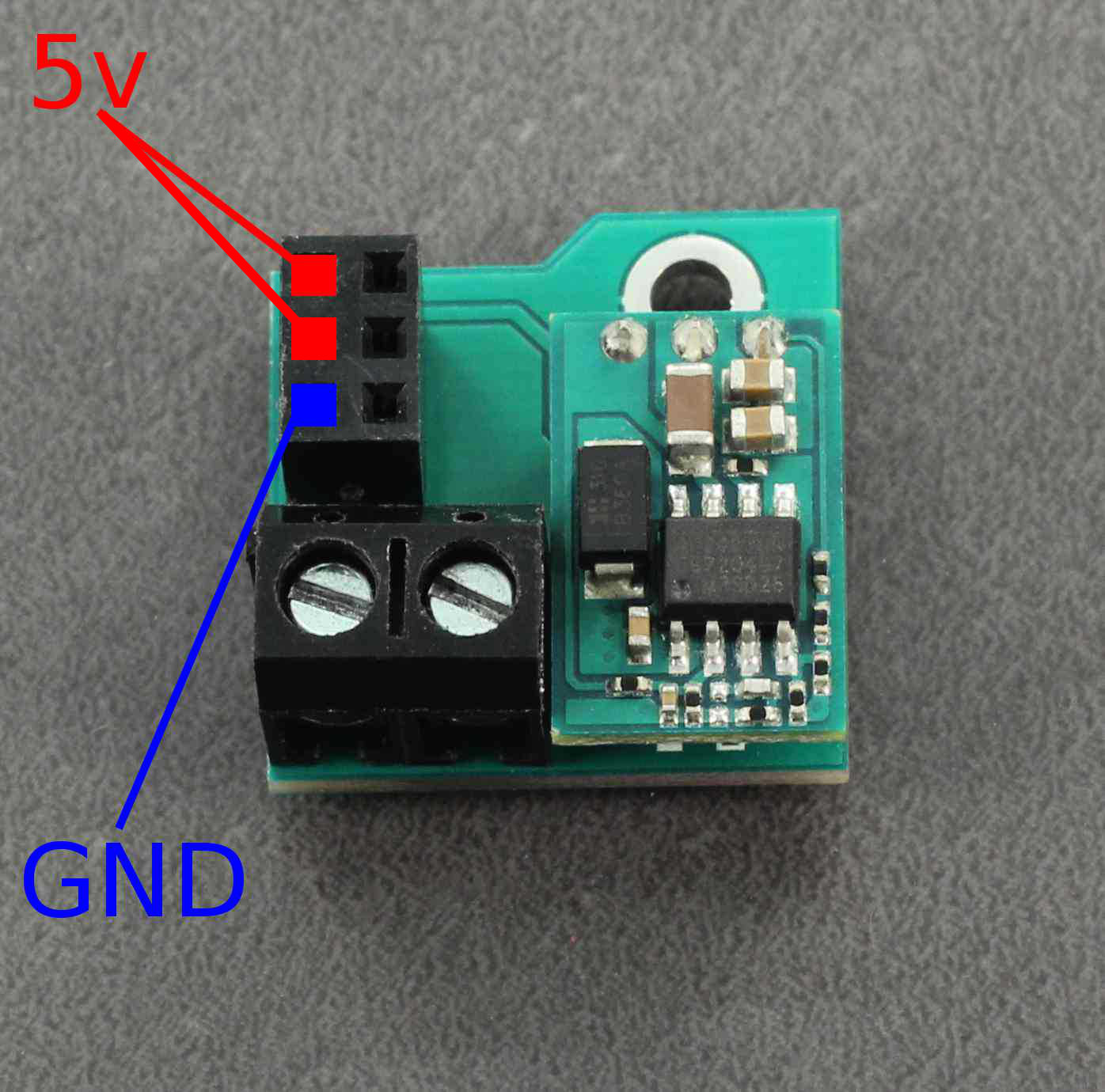
This should be enough to power the Raspberry Pi itself.
Next you want to connect the UltraBorgs.
Start by connecting the 3-pin cable labelled #1 below.
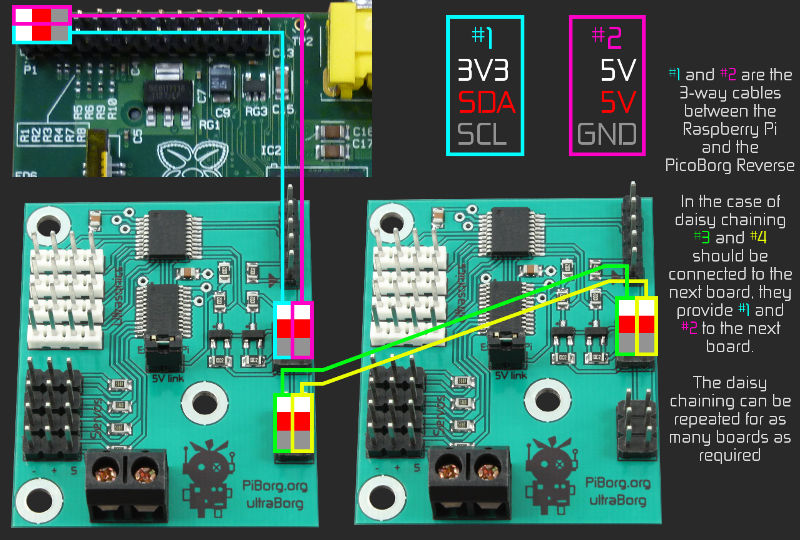
The UltraBorg still needs one of the 5V pins and the GND pin connected. You can connect to the unused 5V pin on the BattBorg and use one of the spare GND pins on the GPIO.
The remaining UltraBorgs can be daisy-chained as normal.
Finally we want to connect the Diablos. There are two options at this point.
Option 1 - share 5V power
Simply connect the Diablos to the last UltraBorg's diasy-chain connector.
This will share the 5V supplies from the BattBorg and Diablos for all of the boards. This may help with the problem you had, but it might not be enough.
Option 2 - Diablos self-power only
In this case we do not connect the 5V pins on the Diablos to anything else. This will isolate the 5V supplies on the Diablos so they only have to power their own on-board logic.
First connect the 3-pin cable between #1 on the diagram below and #3 on the UltraBorg diagram from earlier.
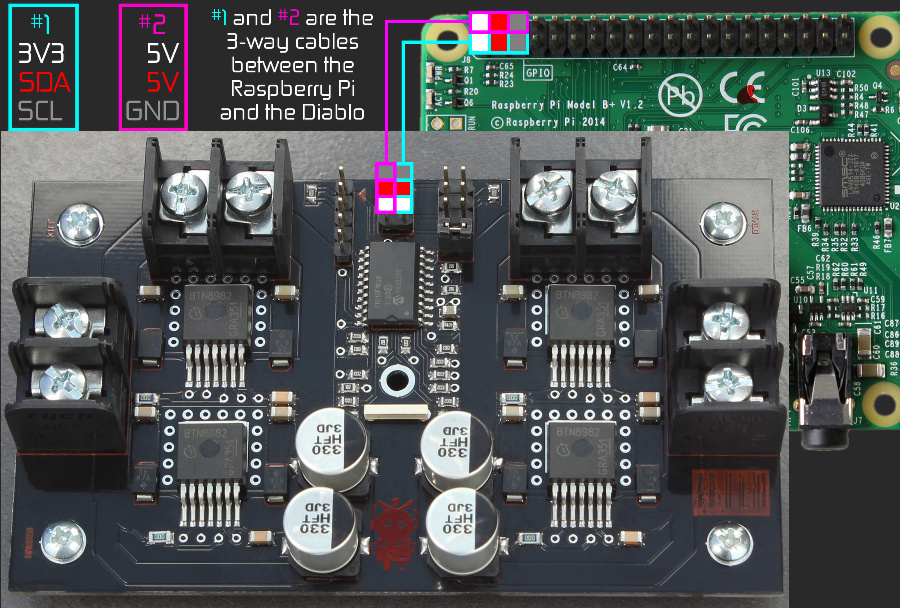
The only other connection that is needed is GND. Connect GND between the Diablo and UltraBorg on the same connector (pin 6)
The second Diablo should then be connected to the first in the same fashion: a single 3-pin cable (3V3, SDA, SCL) and a single pin connection for GND.