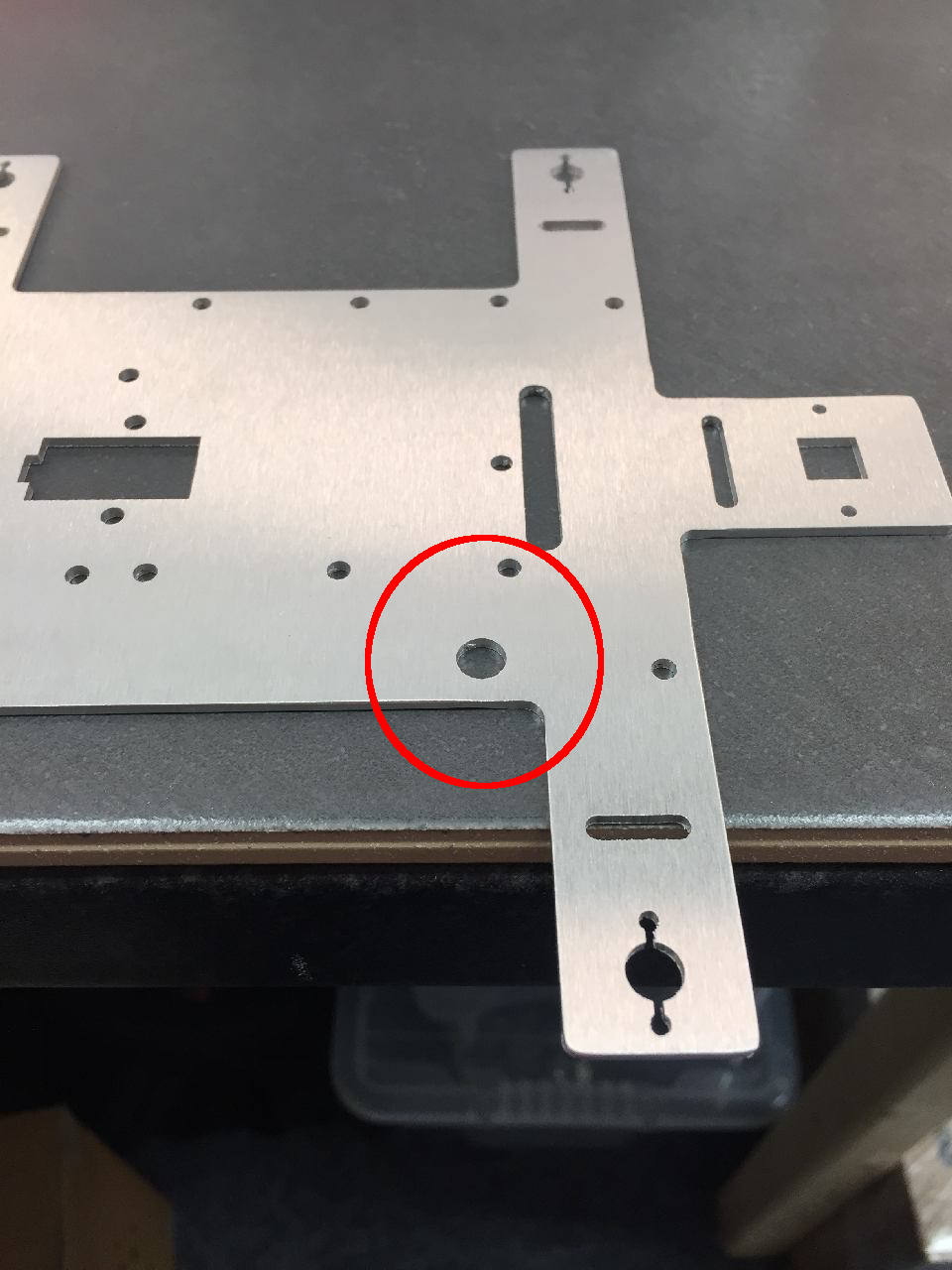
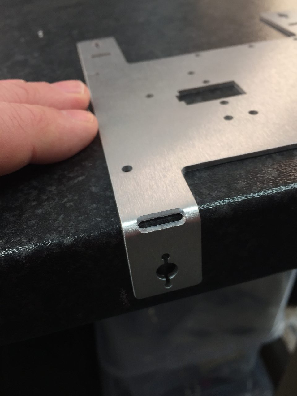
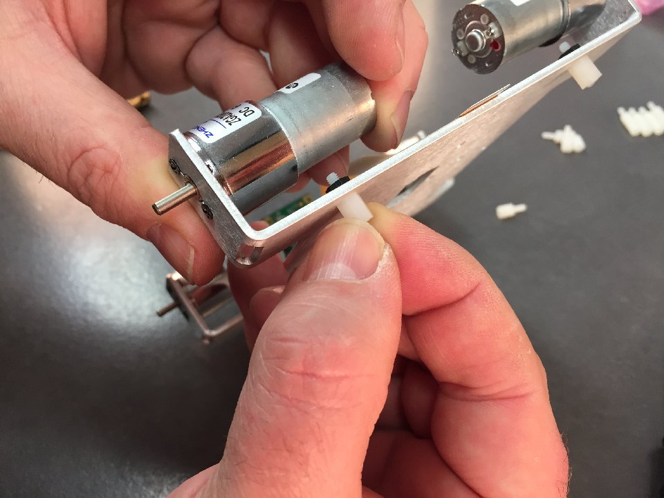
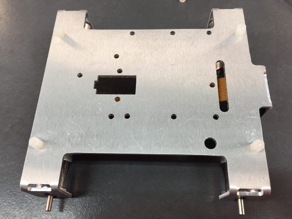
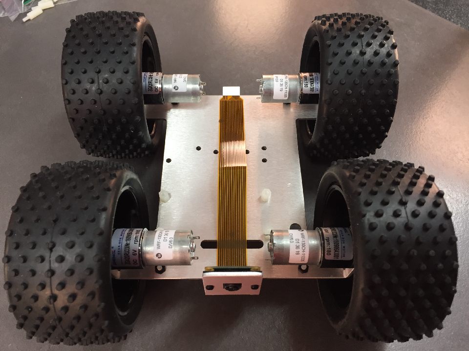
Place the chassis on a table and make sure it is oriented as per picture. Take particular note of the switch hole.
Locate the edge of the table to be central in the bend slot.
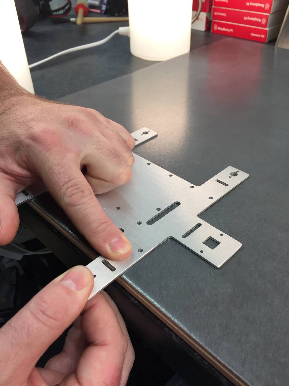
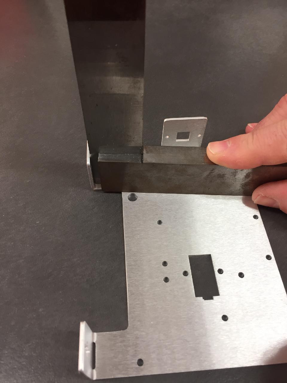
Make sure one finger is firmly holding the chassis against the table.
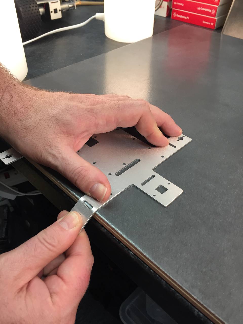
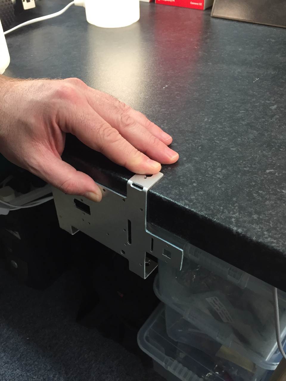
Push down firmly to bend the motor arm.
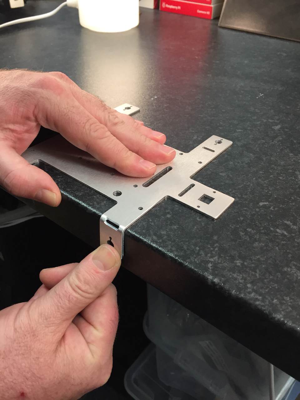
Keep bending until the arm is at 90 degrees.
A thick table is best for making sure this is at 90 degrees.
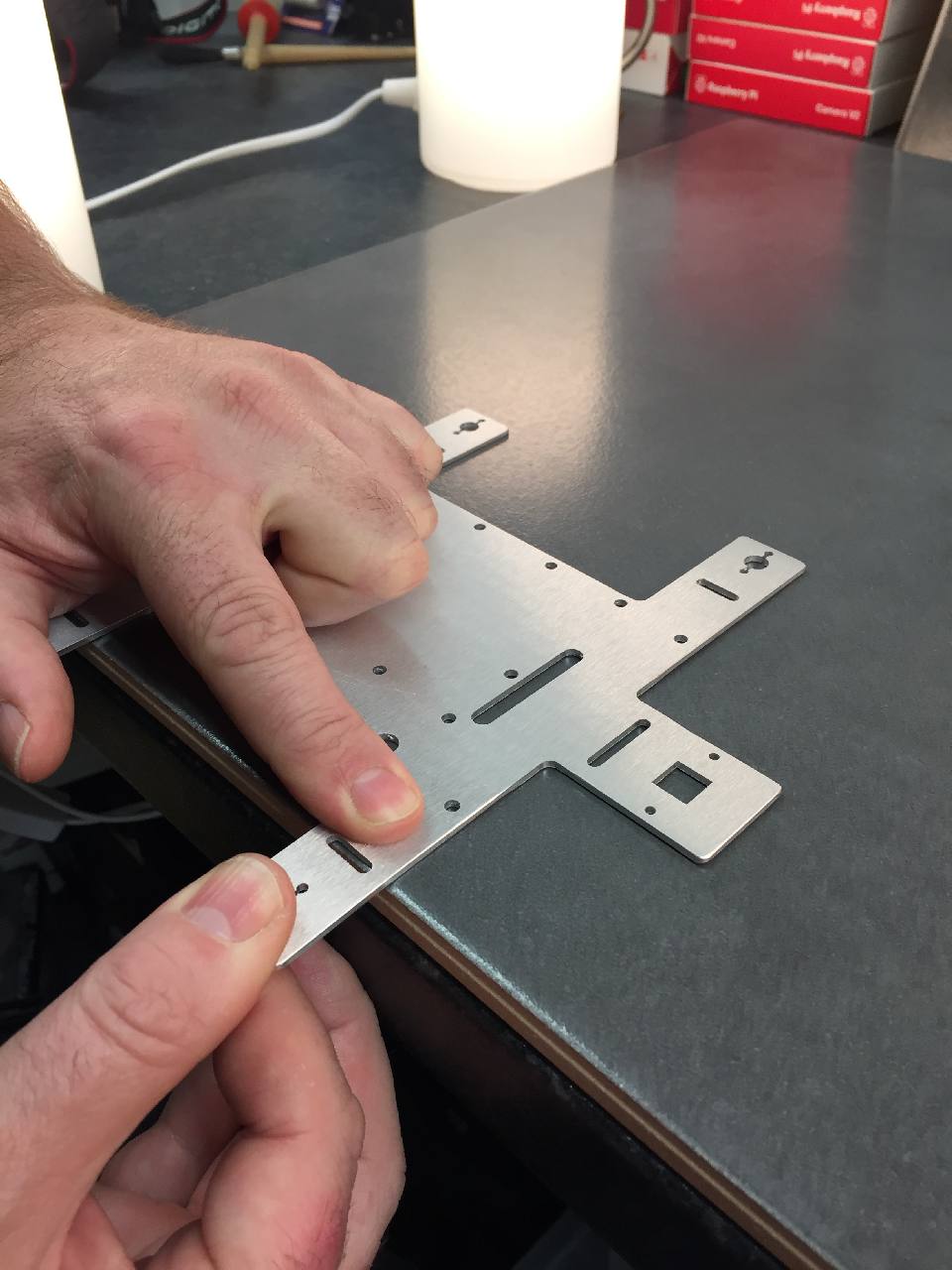
Repeat this for the rear motor arm.
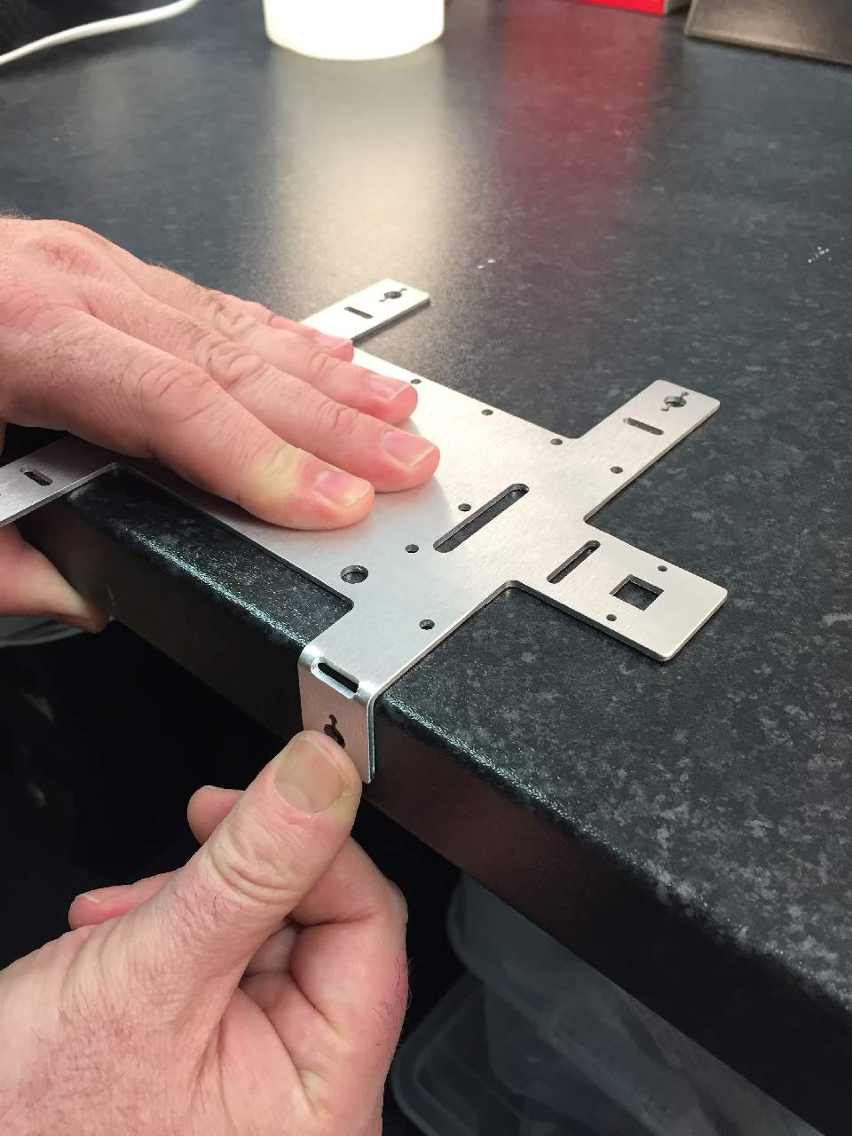
Repeat this for the other side, however this time bending the chassis down from the arm being located on the table.
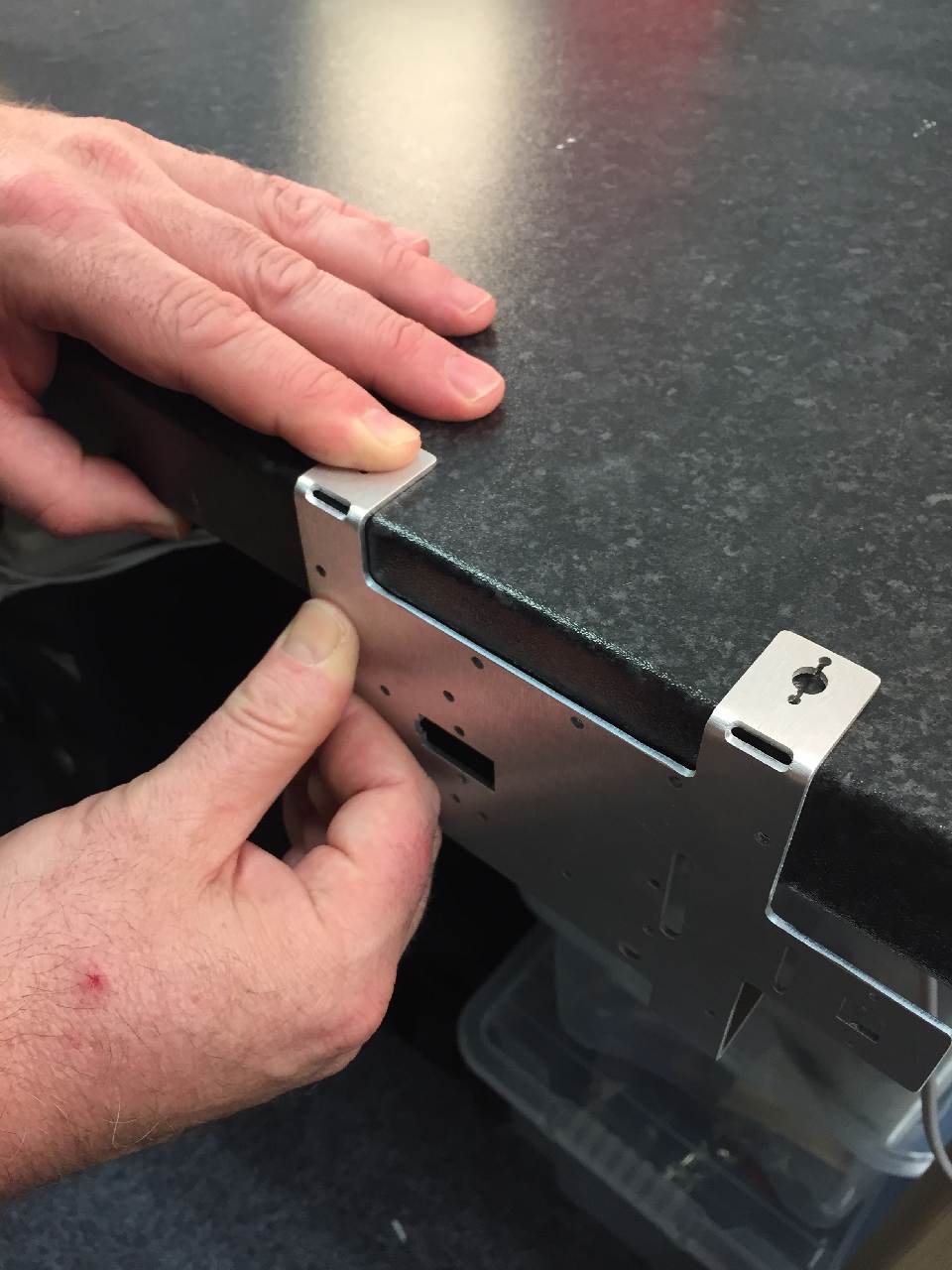
Again, bend from arm to chassis, for rear arm.
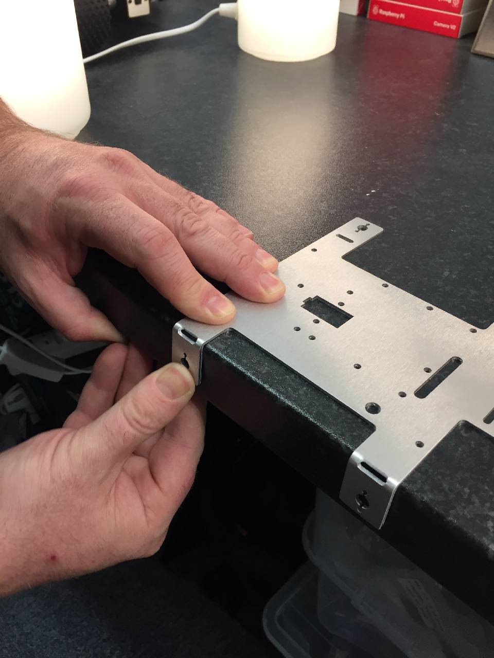
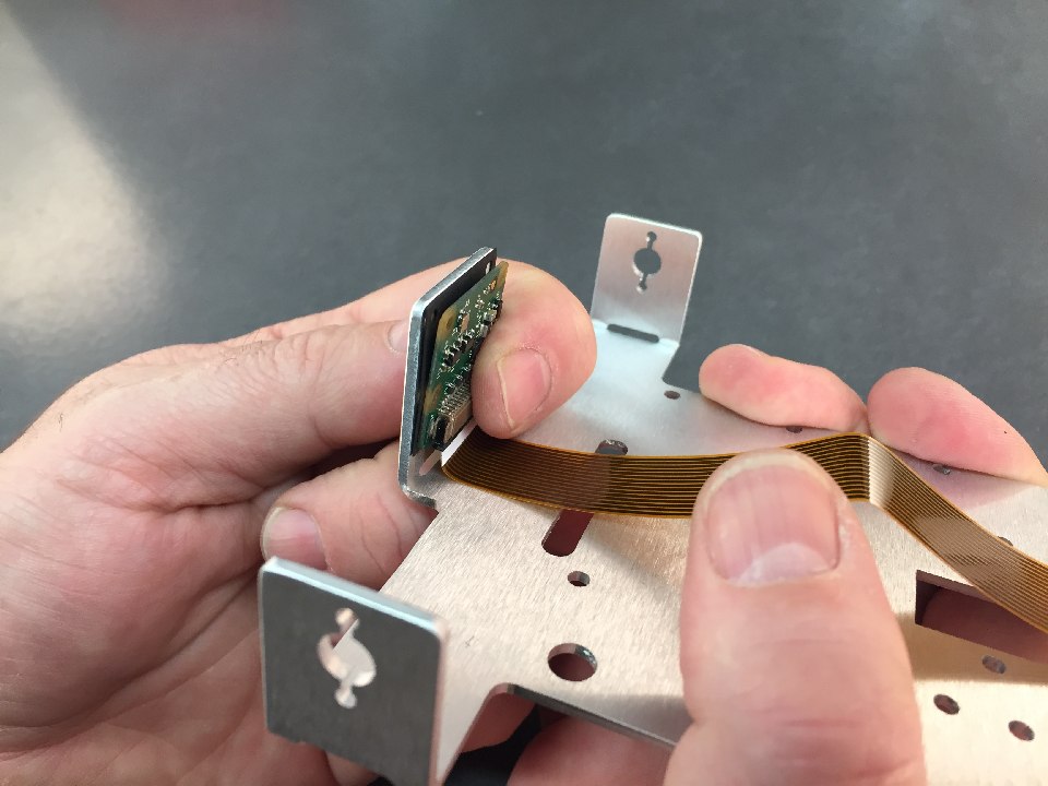
The camera tab will also need to be bent.
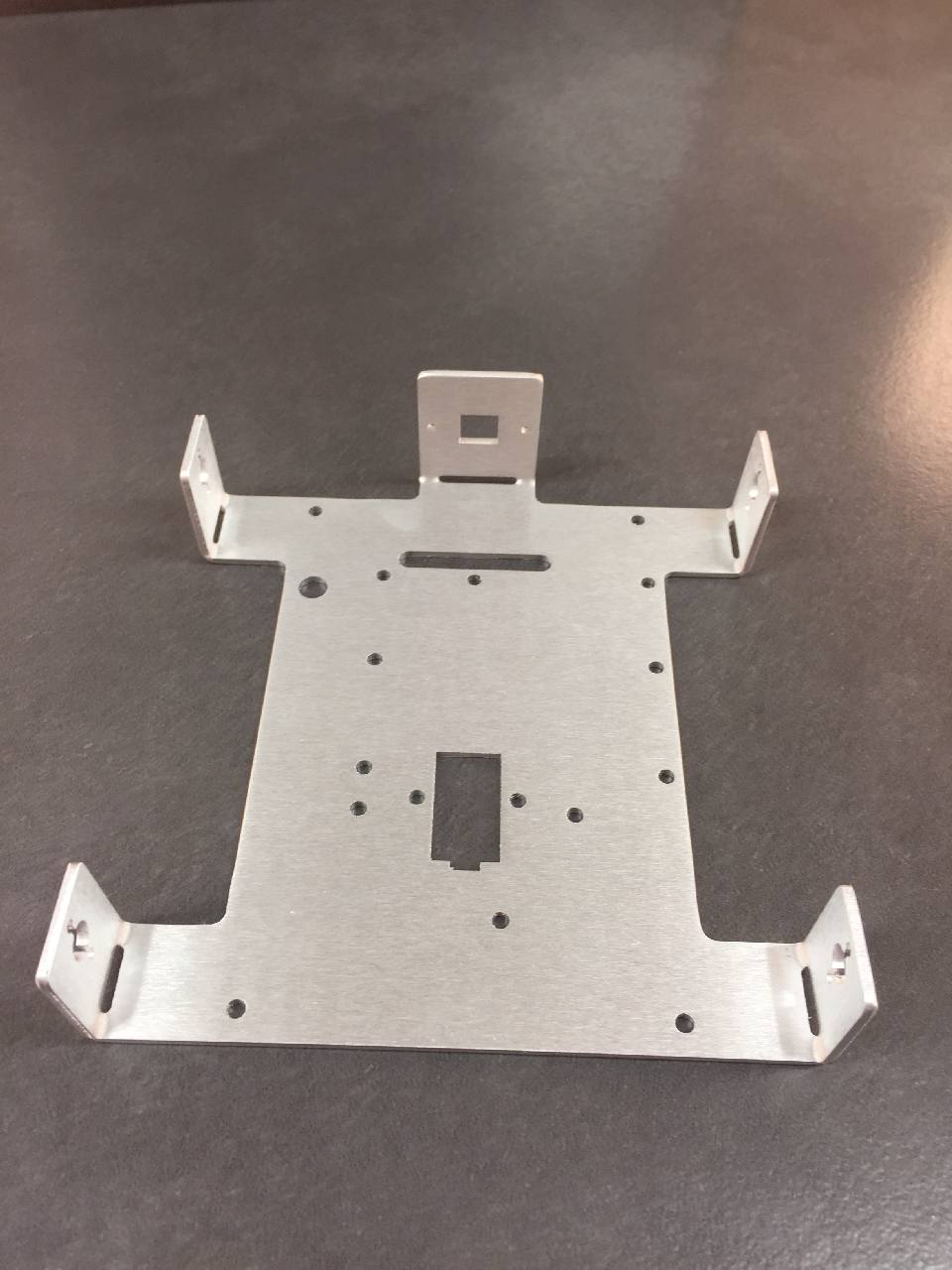
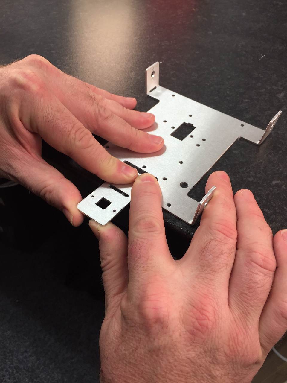
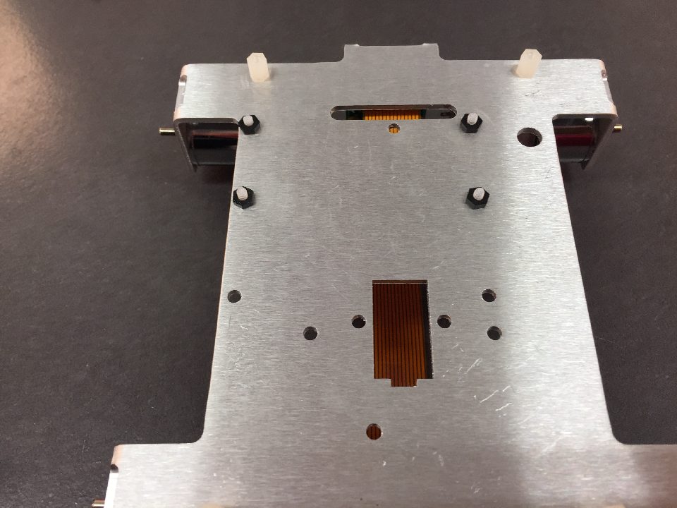
The bent arms should look like this
If you have a straight edge, use it to make sure your bends are at 90 degrees. If not, use a book or something with a definite 90 degree bend. Maybe a Rubiks cube?!
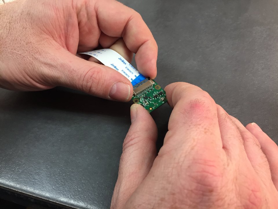
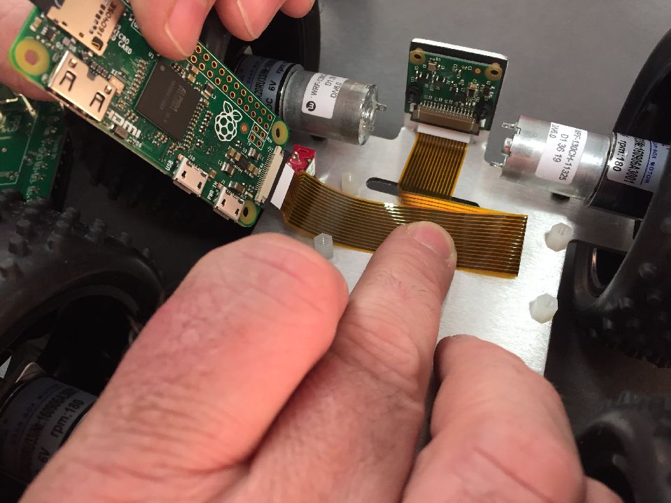
The Pi camera comes with the cable for the Pi3. Remove this by very gently sliding the black holder to the open position as per picture.
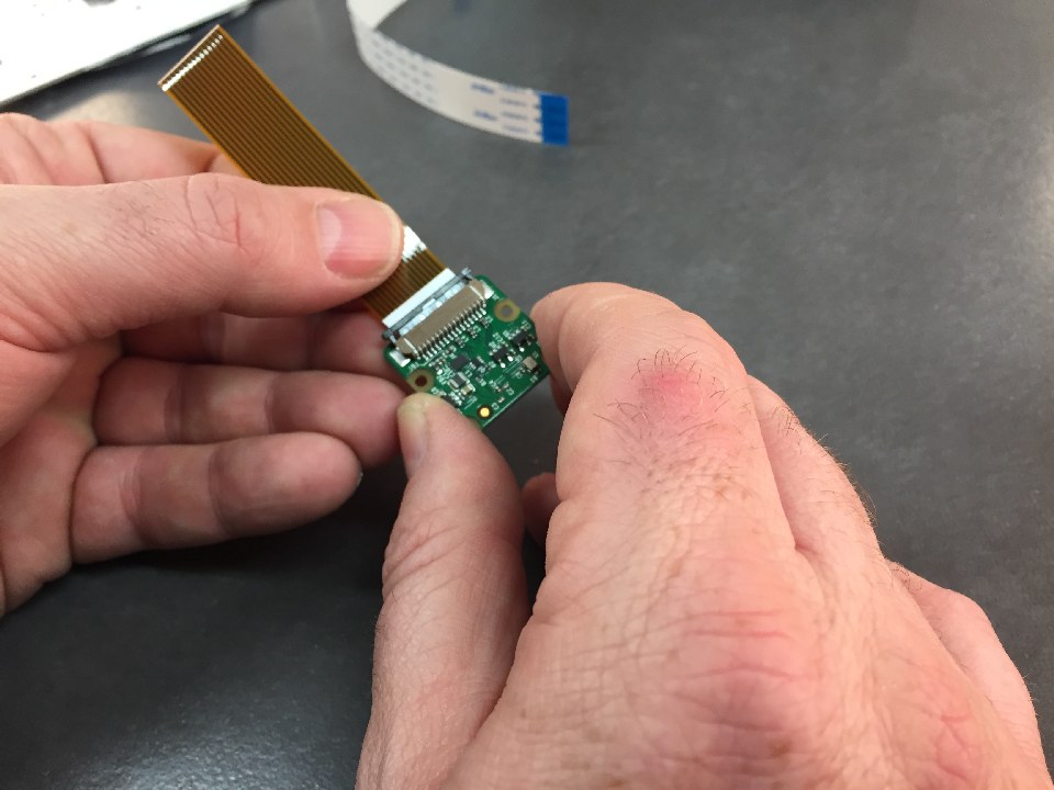
Insert the Pi Zero cable with exposed connectors facing downwards.
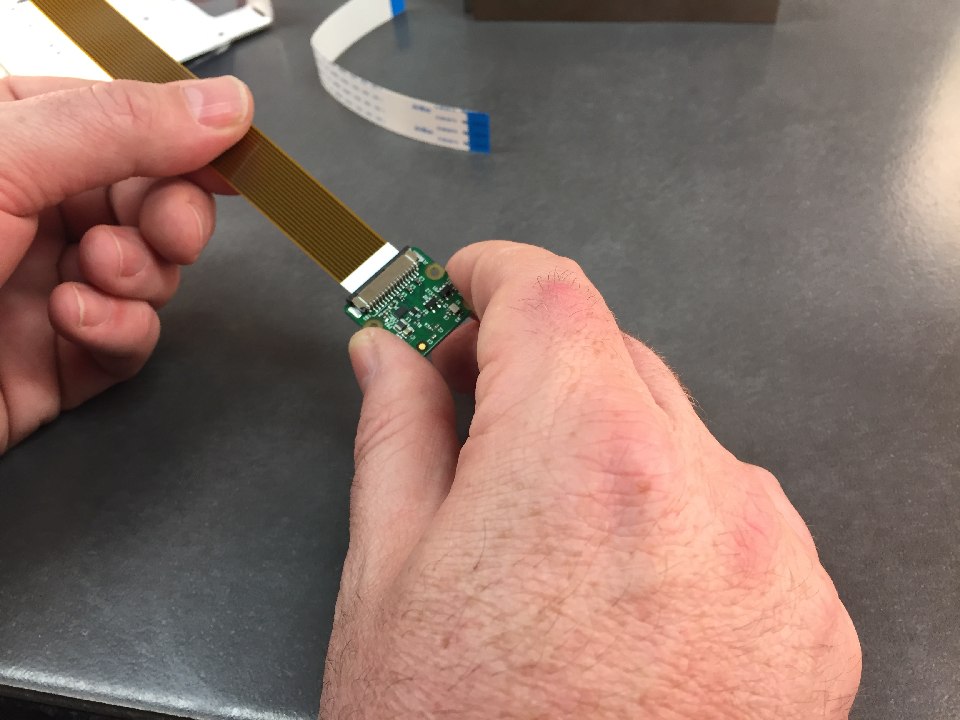
Once the cable is straight in the slot, gently push the black holder back into the closed position.
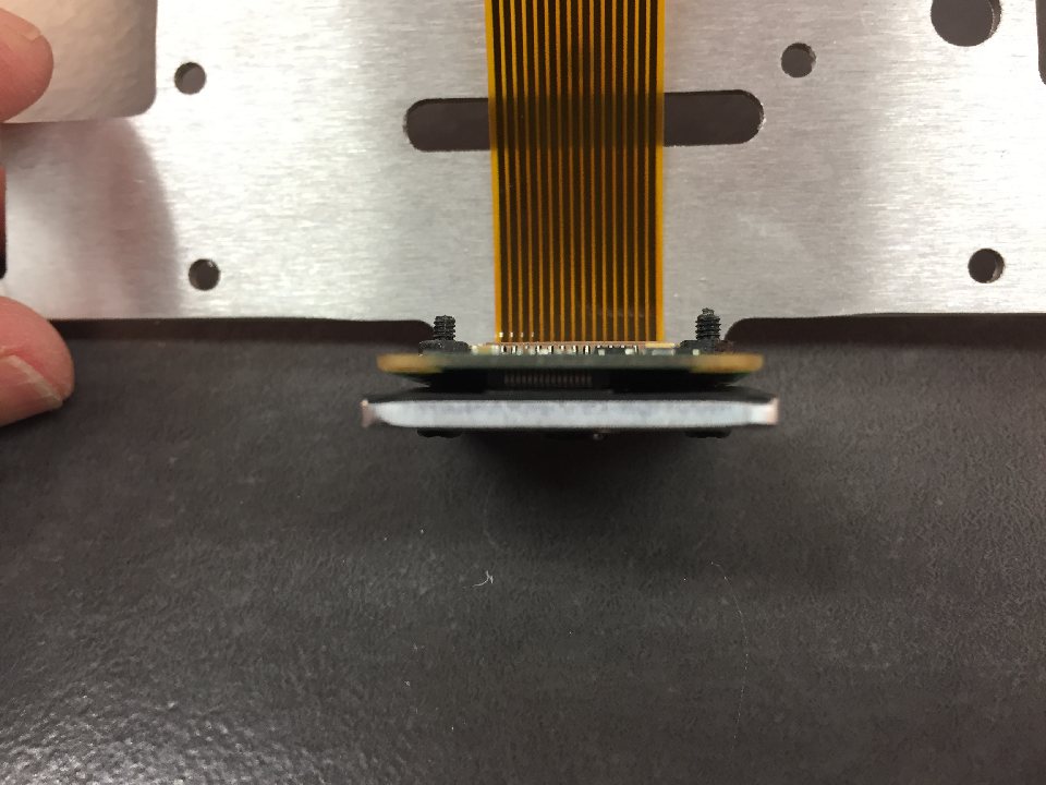
Place the protective fibre panel over the camera.
Make sure the holes line up for the camera screws.
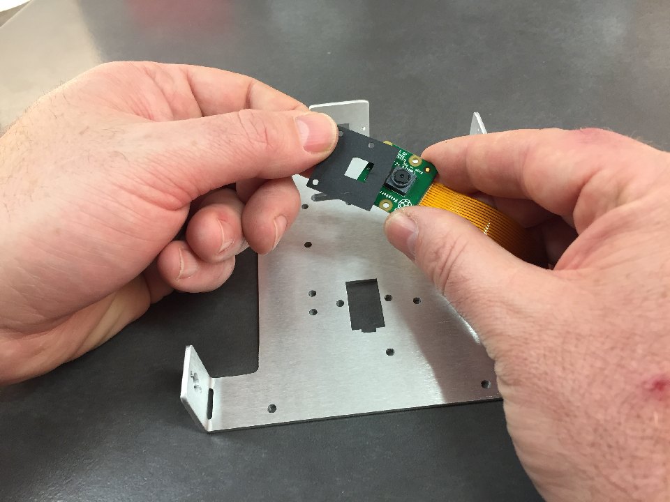
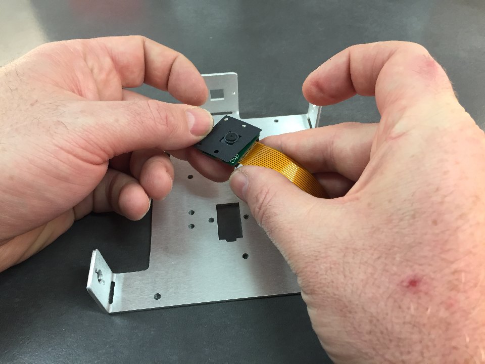
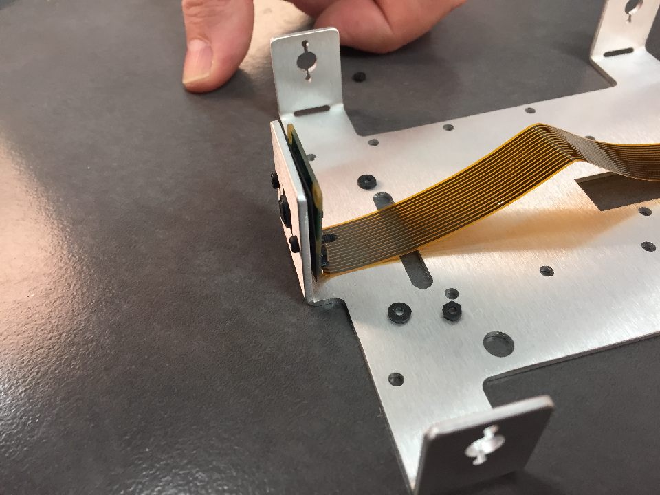
Place the camera in the camera slot of the chassis. This should have the flex cable facing towards the bottom of the chassis as per picture.
Place the two M2.5 screws in the through the camera holes from the front.
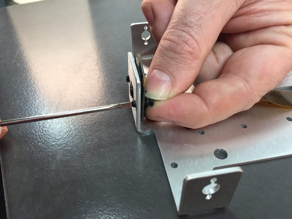
Add the washer and then the nut. Tighten the nut from the front gently. This is a very fiddly part of the assembly!
Very gently tighten until it is secure. You should not be bending the camera board. If you do, it is too tight.
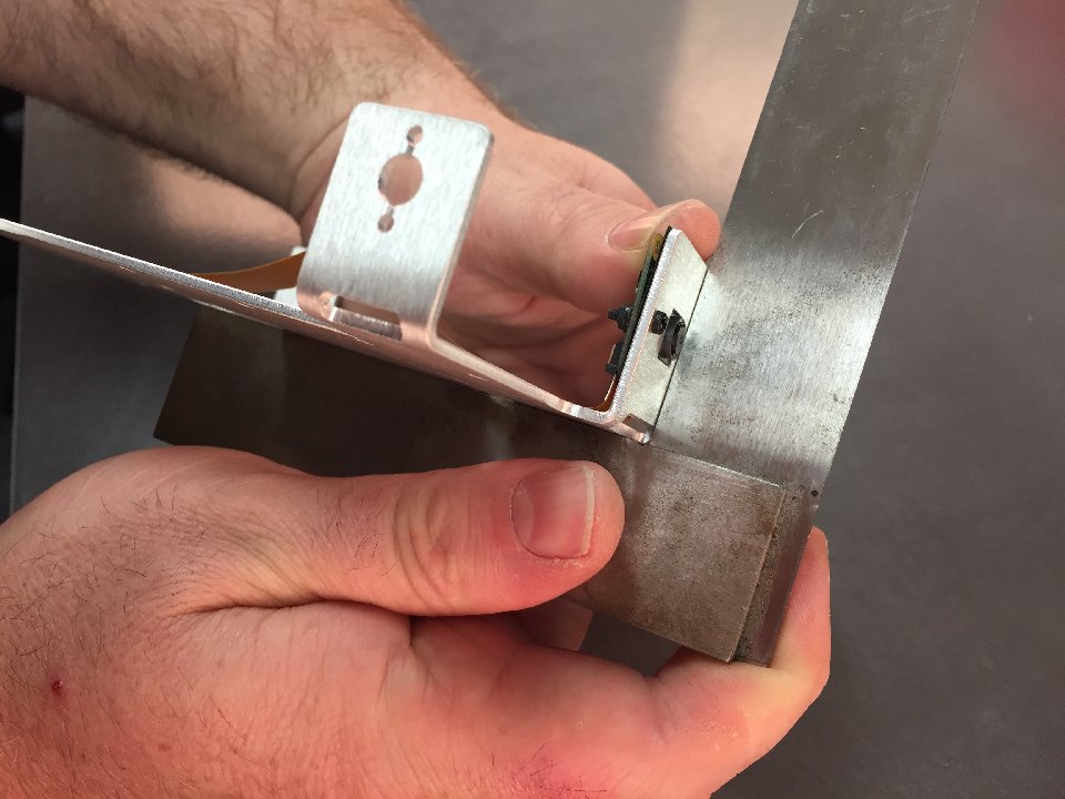
Again, check the bend is still 90 degrees as installing the camera may have moved this.
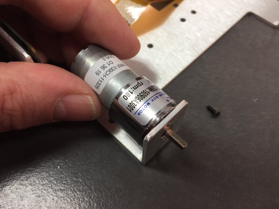
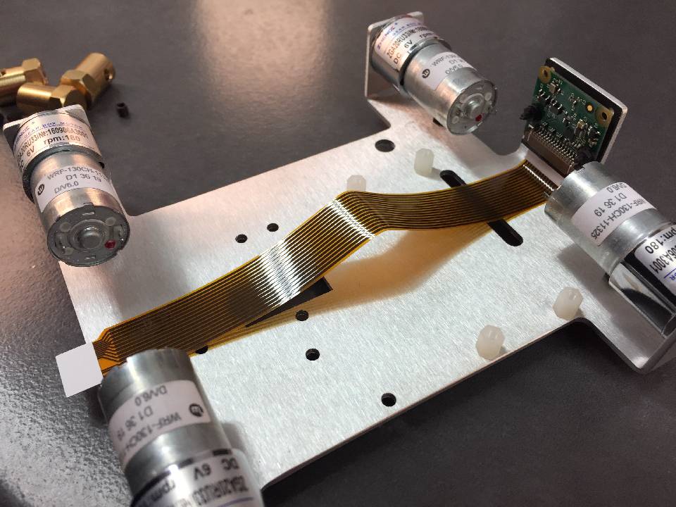
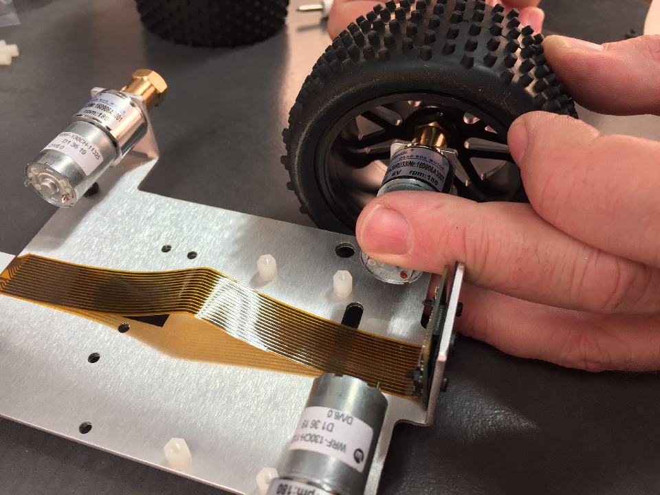
Place the motor in the slot.
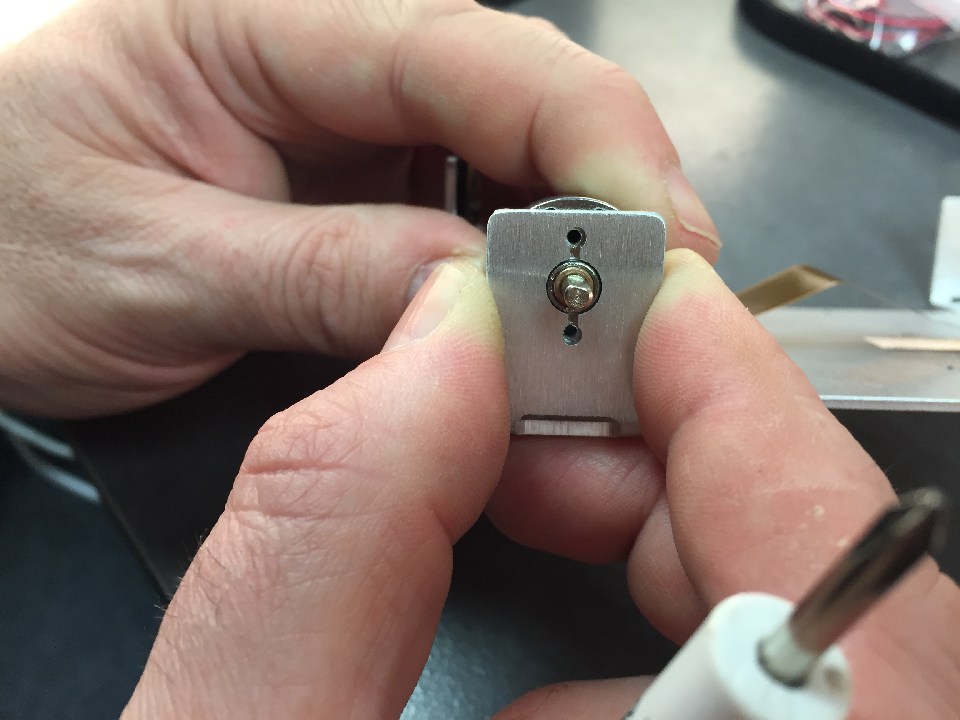
Line up the holes for the motor mount to the holes in the chassis arm.
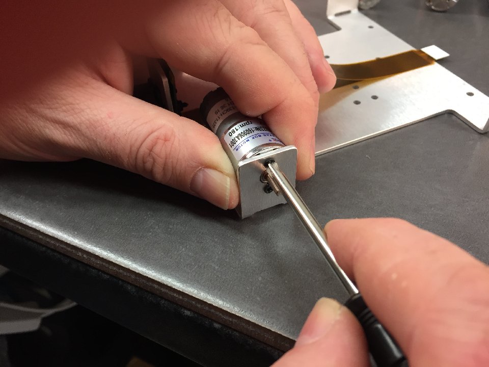
Place in one of the black screws in a few turns (don't tighten yet). Place the second screw in and tighten. Then tighten the first screw.
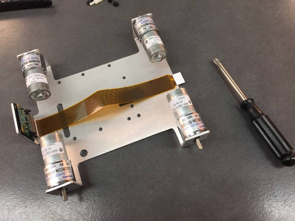
Repeat this for all 4 motors.
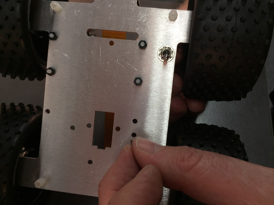
Place the m2.5 posts in the outer 4 chassis holes. The m2.5 nut should be on the motor side.
This is the location for the 4 holes.
Add another 4x m2.5 posts, this time from the motor side, adding the nuts on the top.
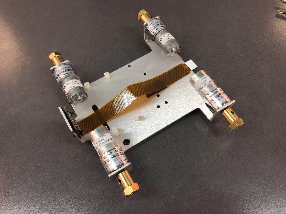
The posts should look like this picture.
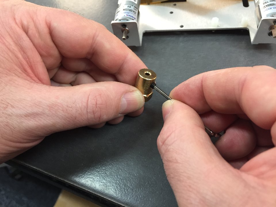
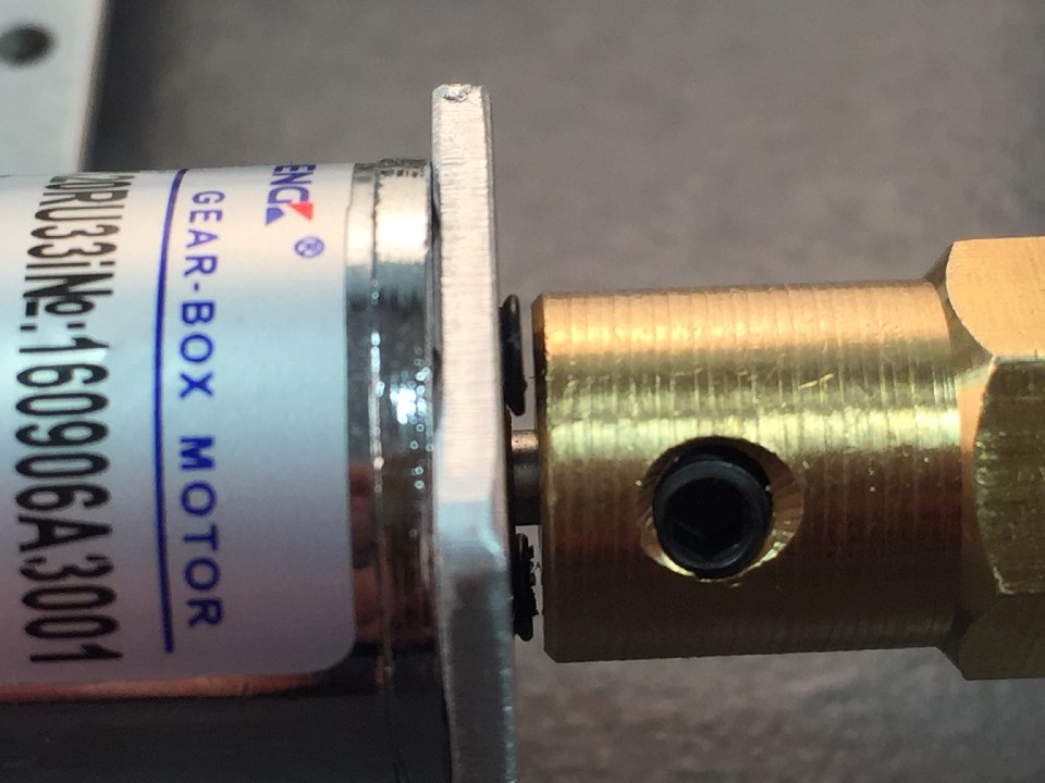
Place the grub screws in the hub, but leave them loose and protruding out as per picture.
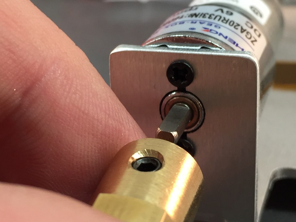
The motor shaft has a flat ground section, and this should be located so that the grub screw will tighten against it. Slide the hub on, very gently tighten, and you should be able to locate the grub screw on that ground part of the shaft.
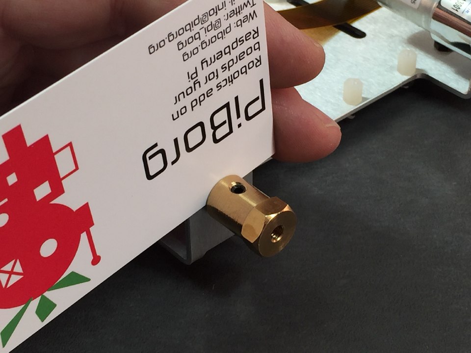
Place the business card between the hub and the motor mount screws. This is the correct gap for the hubs. Tighten both grub screws.
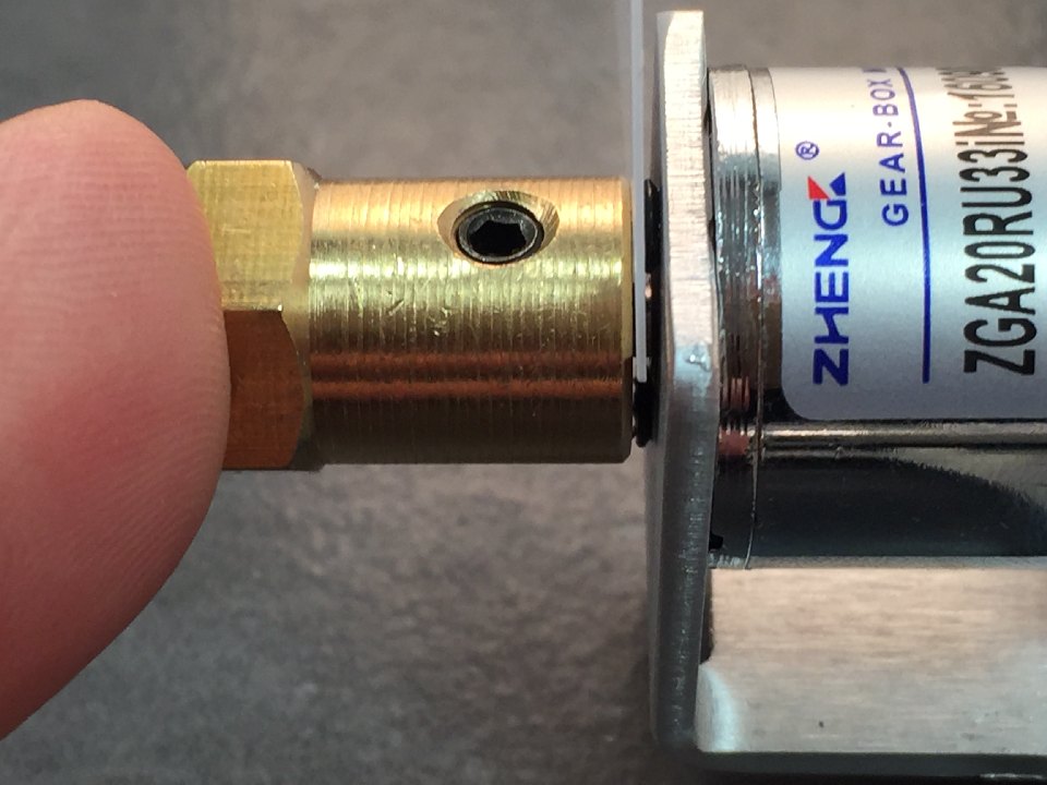
Again the gap between the hub and the grub screws should be the business card. They should be straight on the shaft. If not, loosen grub screws and try again.
Once the business card is removed you should see a small gap. The hub should not rub on the motor screws, otherwise loosen and try locating again.
Repeat for all 4 motors.
Place the wheel on the motor, making sure the hex pattern in the hub and motor line up with each other.
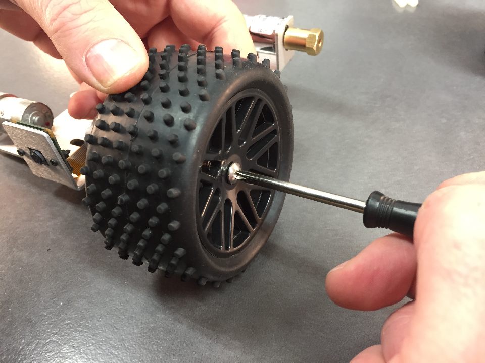
Add the M4 screw and tighten well holding the wheel as you tighten.
Repeat for all 4 wheels.
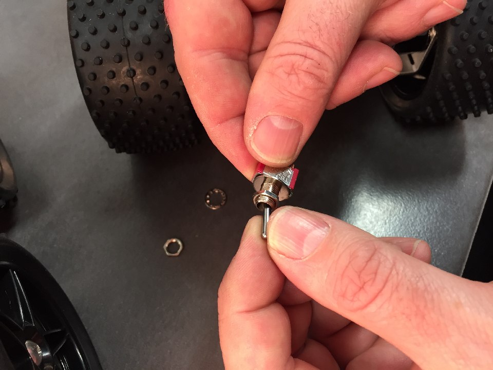
Disassemble the switch, leaving just one nut on it.
Place in the switch hole, and add the lock washer over the top.
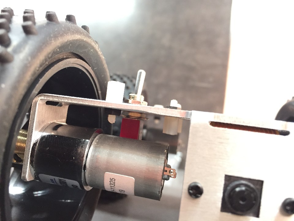
Add the nut on the other side. Locate so that the switch on/off direction is parallel with the direction of travel of the robot.
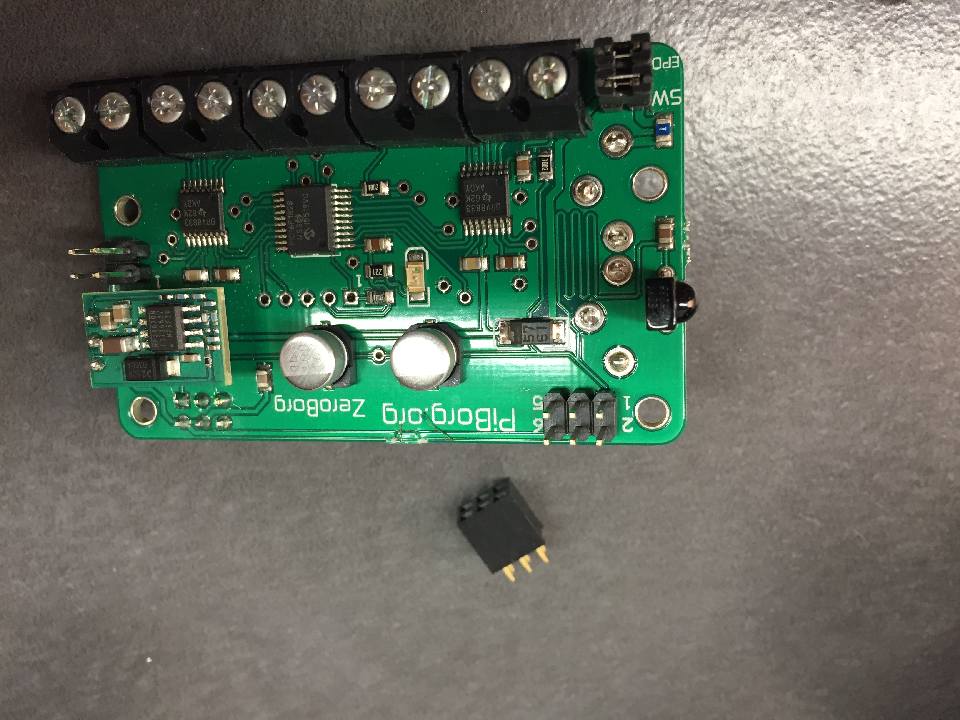
From your ZeroBorg, place the 6 pin female header on the top 6 pin make header.
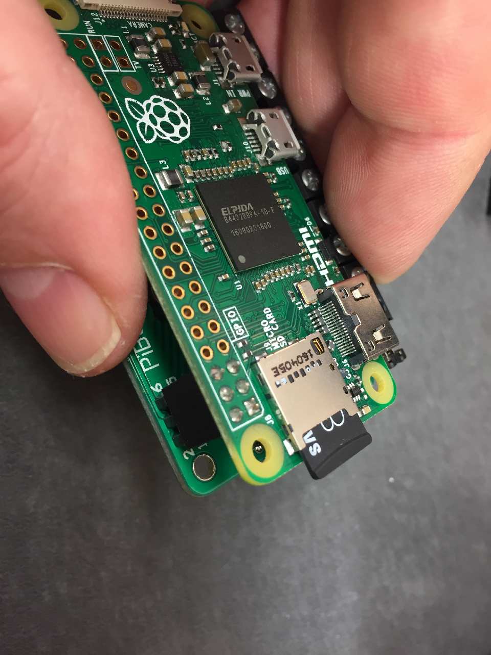
Place the Raspberry Pi Zero over the top and solder on the 6 pin header.
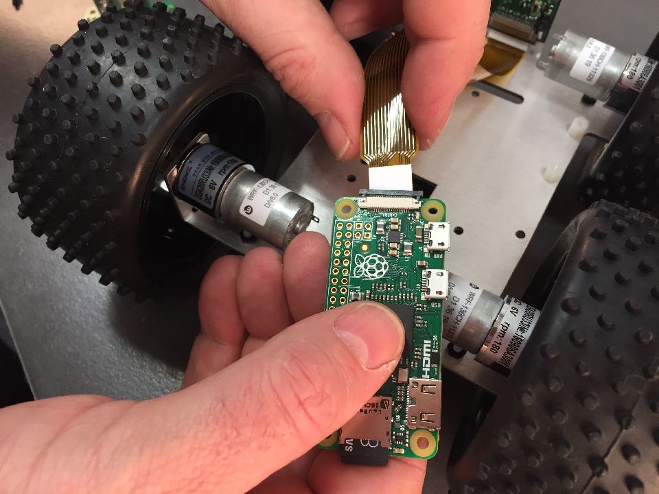
Gently pull the black holder to the open position and insert camera cable. Make sure the cable is oriented to have the white strip pointing up and the contacts pointing down.
Make sure the cable is straight and gently push the black holder back into the closed position.
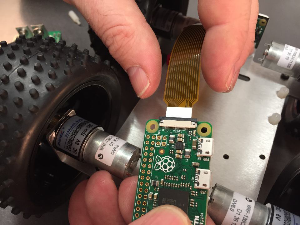
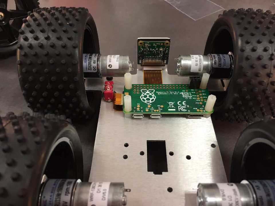
Very gently fold the flex cable to the pattern as pictured. Don't put too much pressure or you could break the cable.
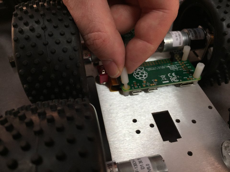
Place the Zero over the posts and add the longer m2.5x12mm posts.
Repeat for all 4 posts.
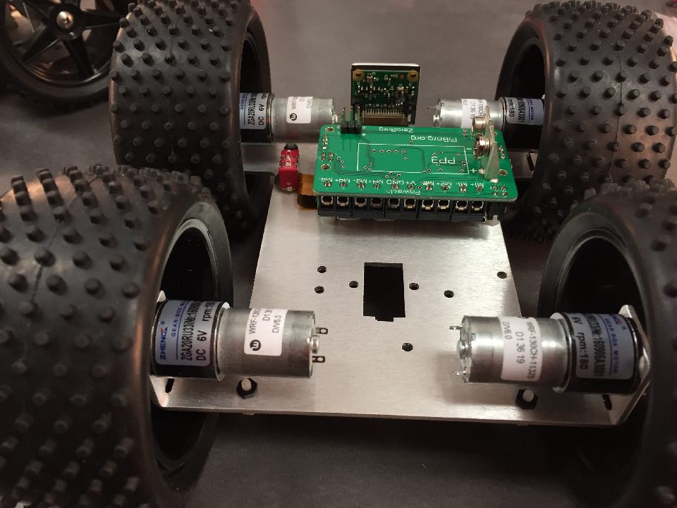
The ZeroBorg should sit above this. Don't screw it in yet, as we need to unplug to connect up the cables.
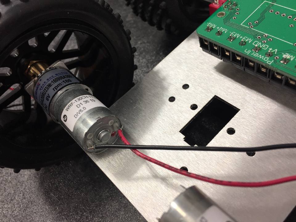
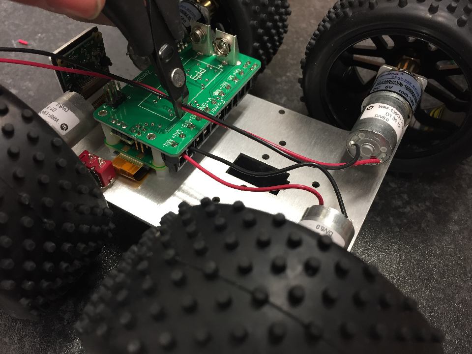
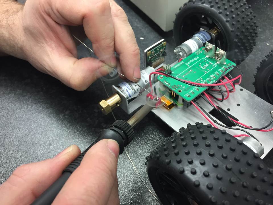
Select the motor farthest from the camera on the switch side. Take a red cable, strip a small amount off the end, and connect it up to the motor terminal next to the red mark. Put the black cable in the other terminal.
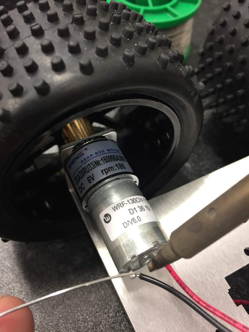
Solder the terminals, making sure the solder does not short to the motor mount.
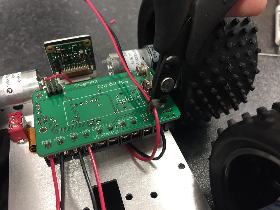
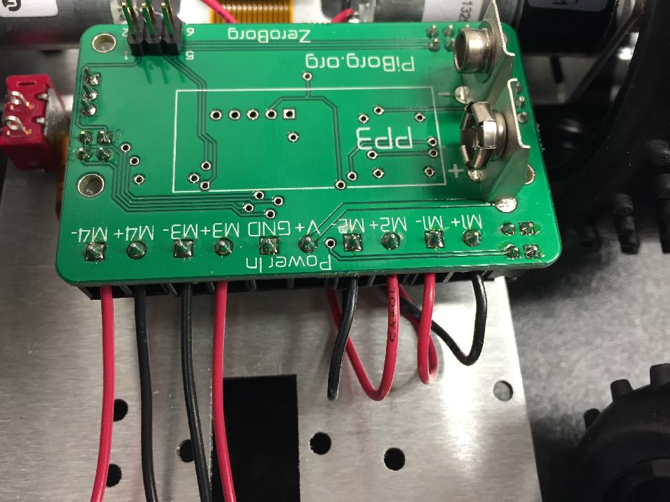
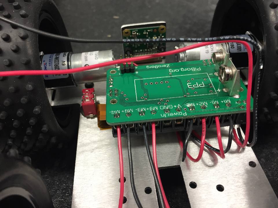
Route the cables back to the M4 terminal. Cut just past the M4 text (approximately in line with the battery outline).
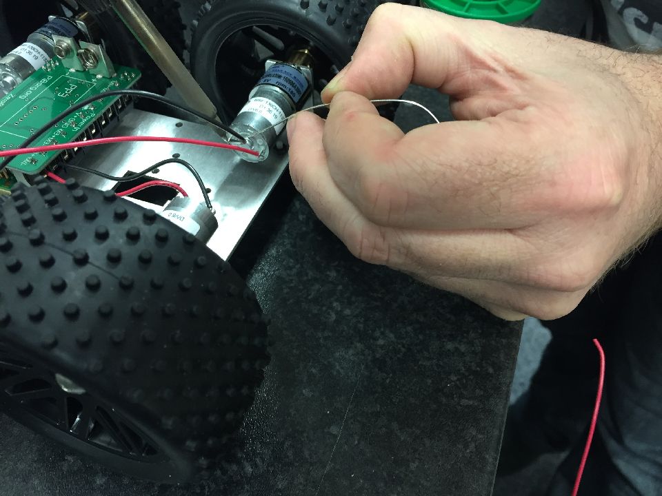
Repeat this for the motor farthest from the camera, on the other side, but using the M3 sockets.
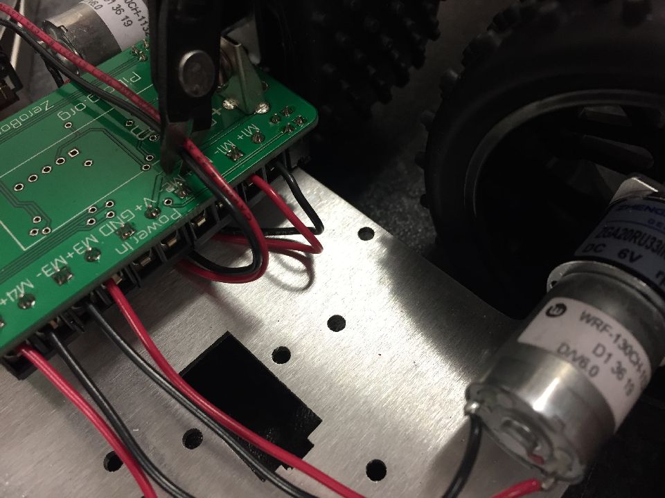
On M3 and M2 Red should go to +, black to -, however we will swap these on M4 and M1 as they travel in the opposite direction.
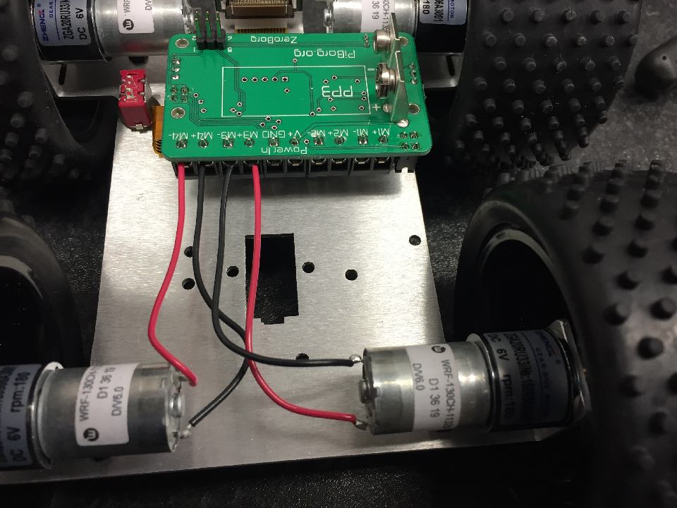
Take note again of the connections (Underside left to M4, Underside right to M3), polarity (+ or -) and the colour (red or black) in the previous step. Strip the ends of the cables and screw in.
Tighten and make sure the cable is pinched underneath the screw terminal (so you can't pull the cable out with a gentle tug).
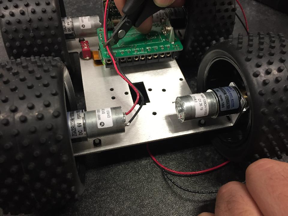
The motor on the switch side at the front (closest to camera), should again have red into the motor terminal with the red dot.
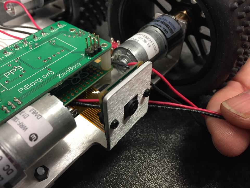
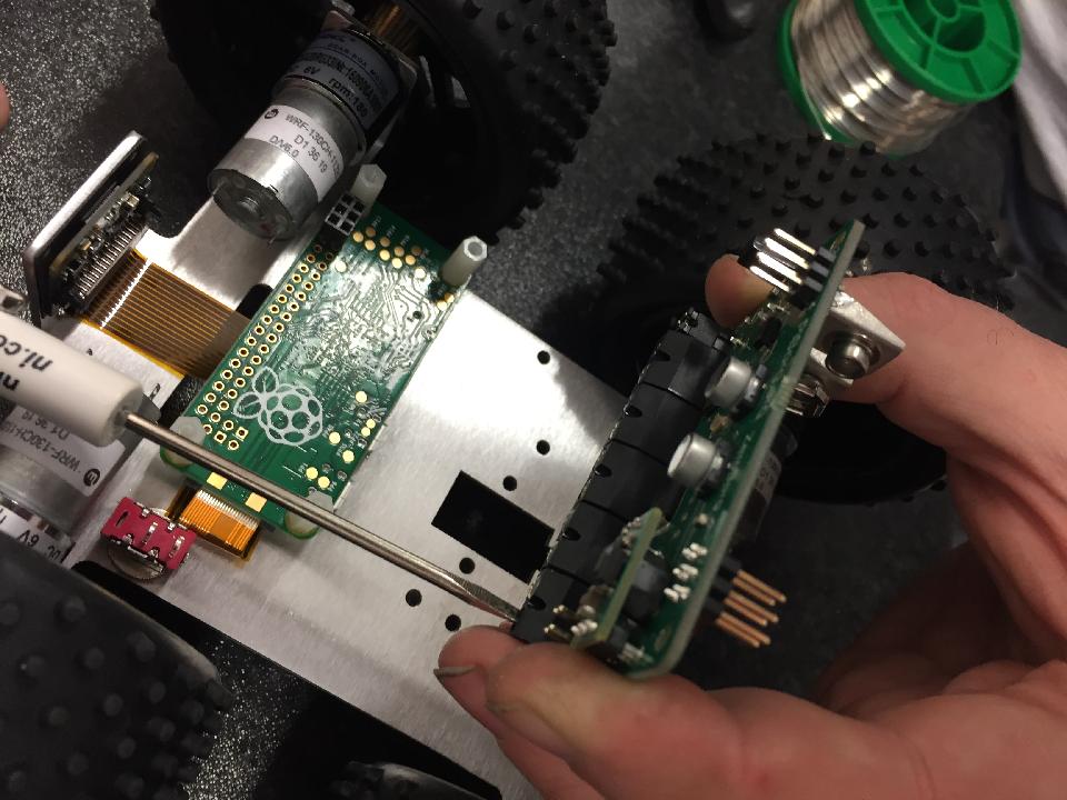
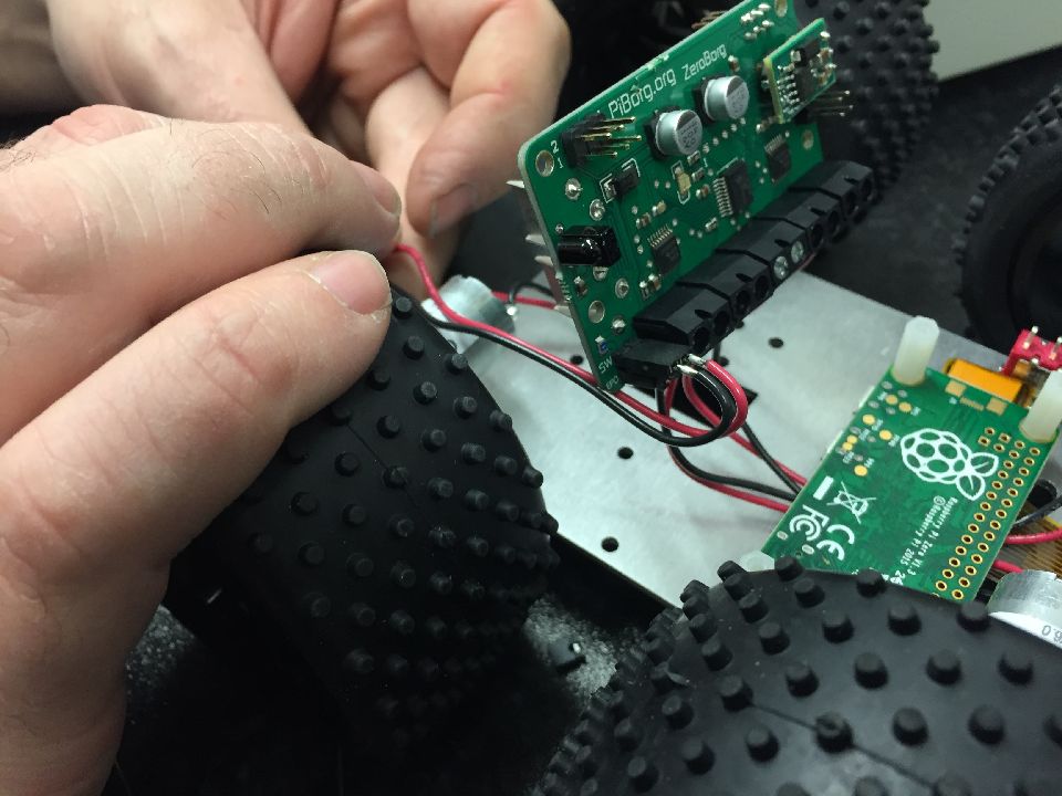
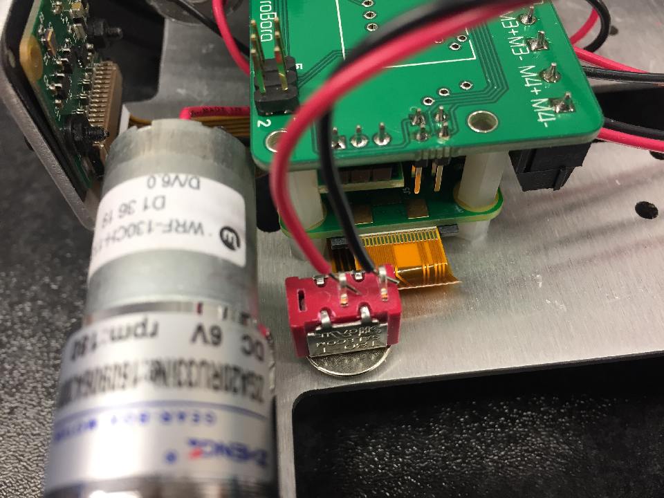
Route the cables back to the terminal side. It's best to route these underneath the Pi as per image. Be careful not to damage the flex cable.
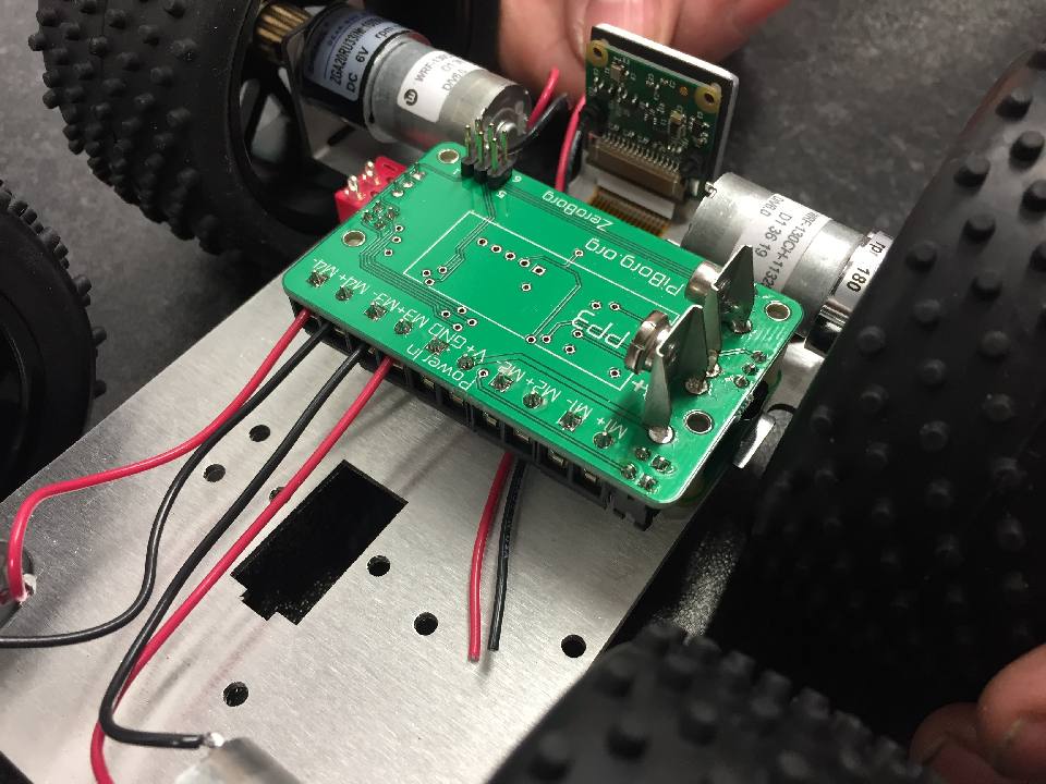
Pull these through,on the right hand side of the power In connector and trim to correct length as before.
*Note* These will plug into to M2 not Power In!
Plug these in - Red into M2+ and Black into M2-
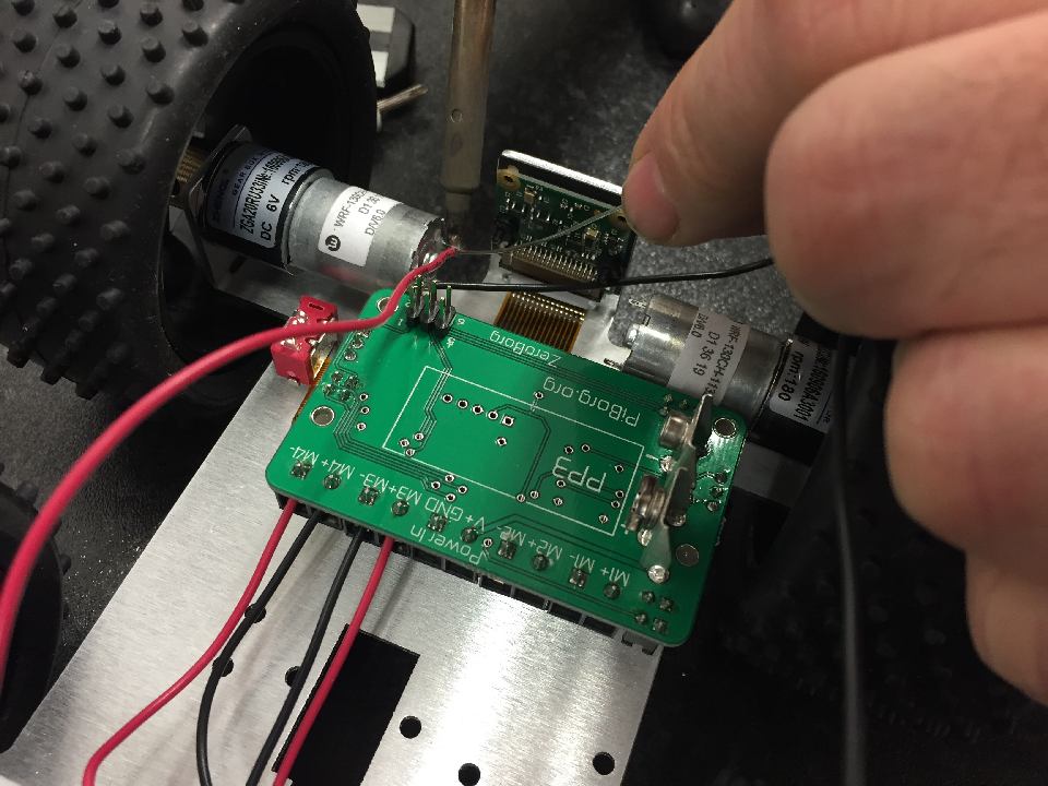
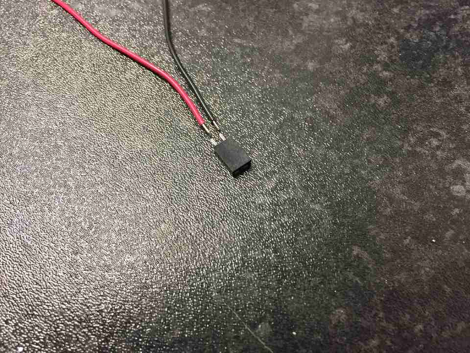
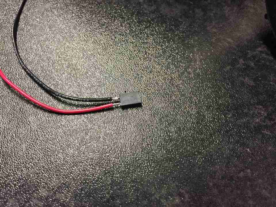
Now we will connect up the switch to the connector. This is fiddly! Strip the wires and sit the red black one ON the metal part of the connector. It doesn't matter which colour is connected to which side of the connector.
Very carefully heat the wire and connector and add a small amount of solder.
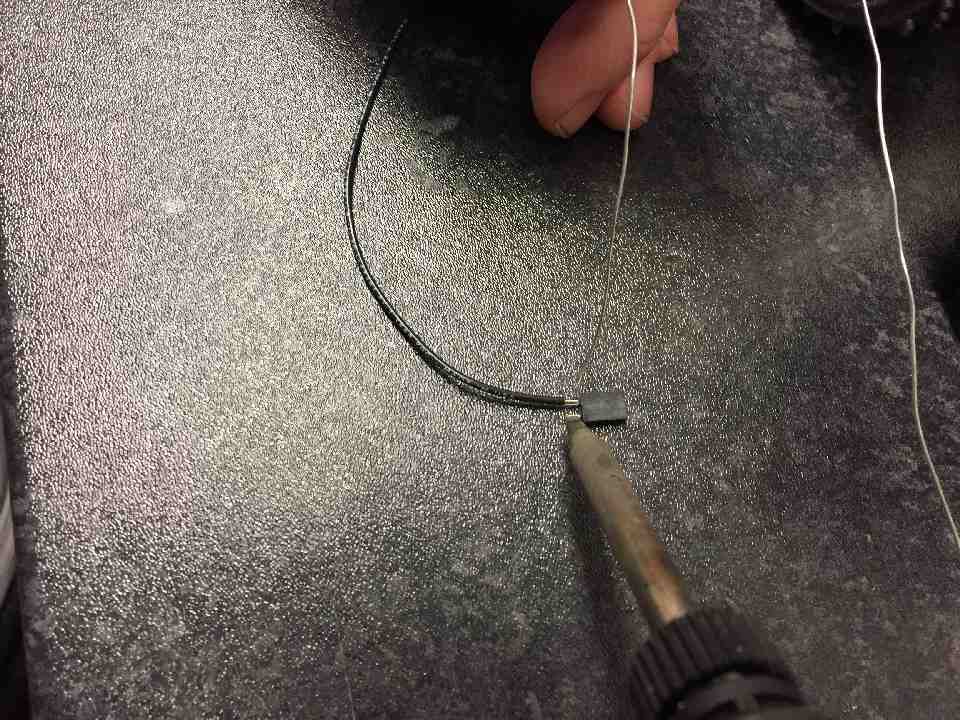
This is a difficult part of the soldering, so take your time.
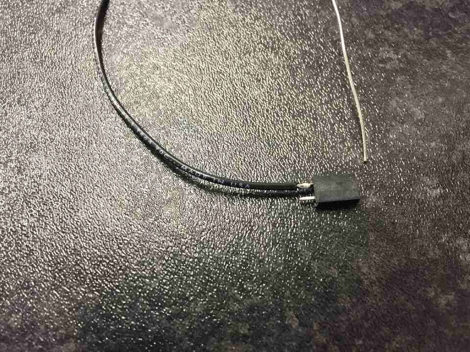
Hopefully it should look like this.
Repeat this for red, strip and rest on connector pin.
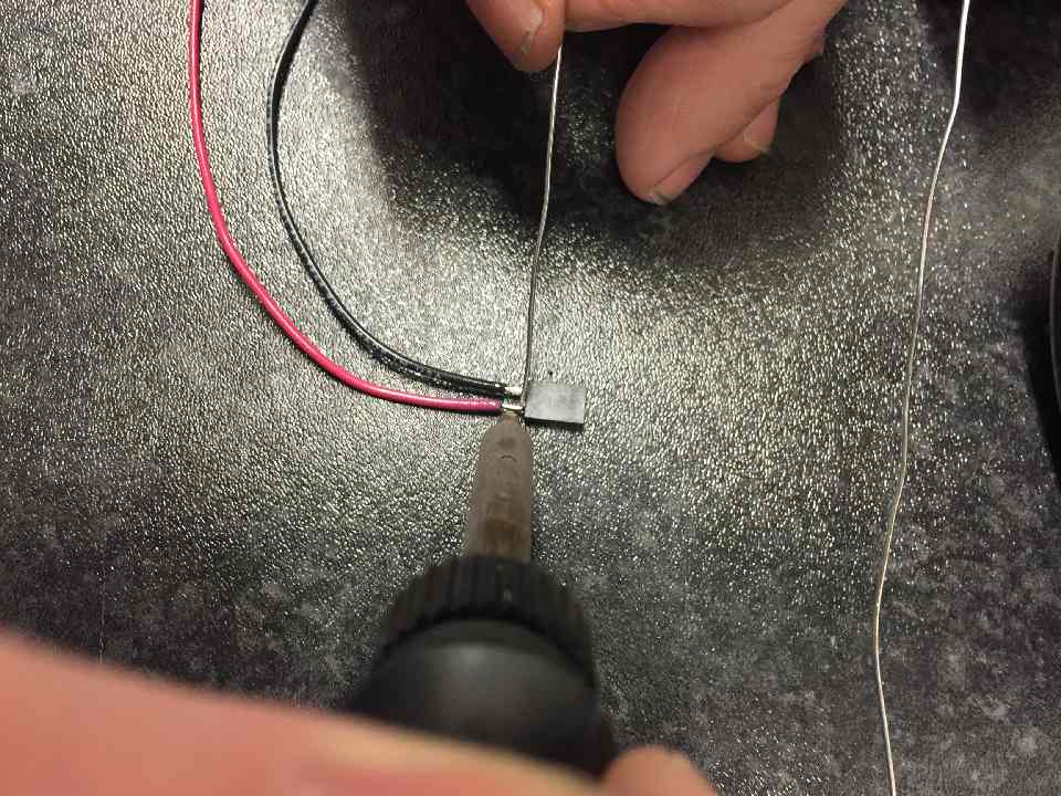
Solder the red cable on
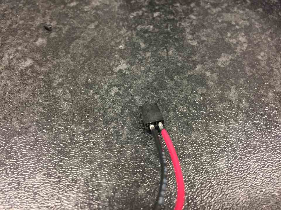
You should have two connected cables, that aren't shorted and do not come undone with a gentle pull.
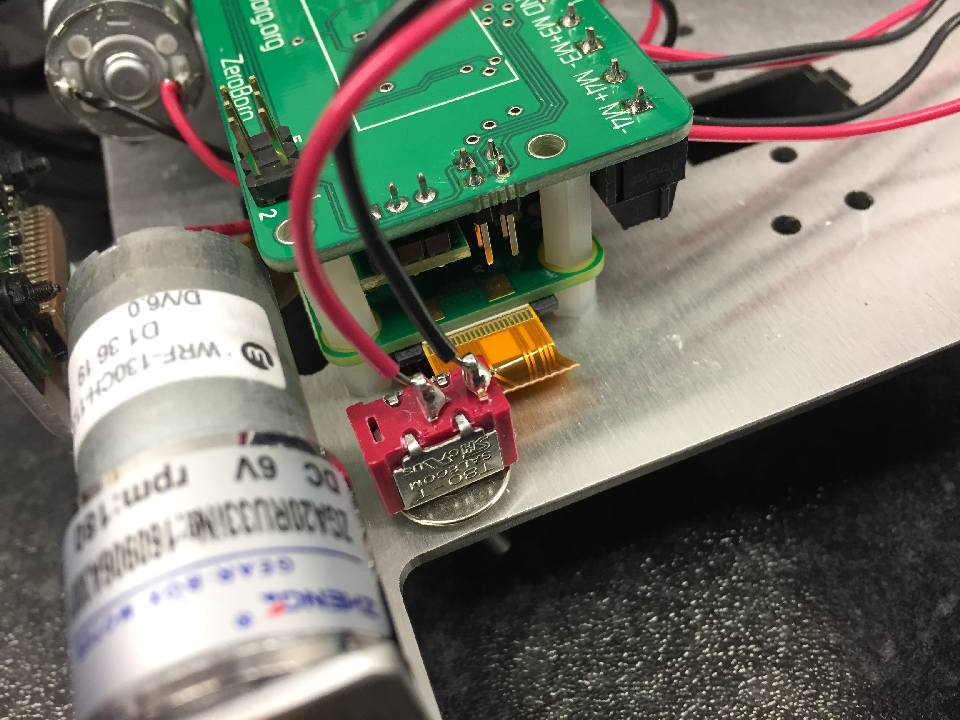
Remove the jumper from the SW connector, and replace with the connector you have just soldered.
Route the cable over the board to the switch.
Strip and place connectors in holes as per picture. Some switches come with three connectors in this case, use center and one side hole.
Solder these connectors in.
Make sure there are no shorts between the connections, and trim off excess wire.
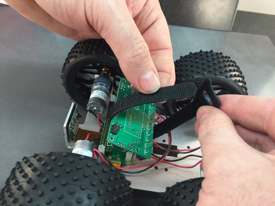
Place the battery holder strap around the ZeroBorg.
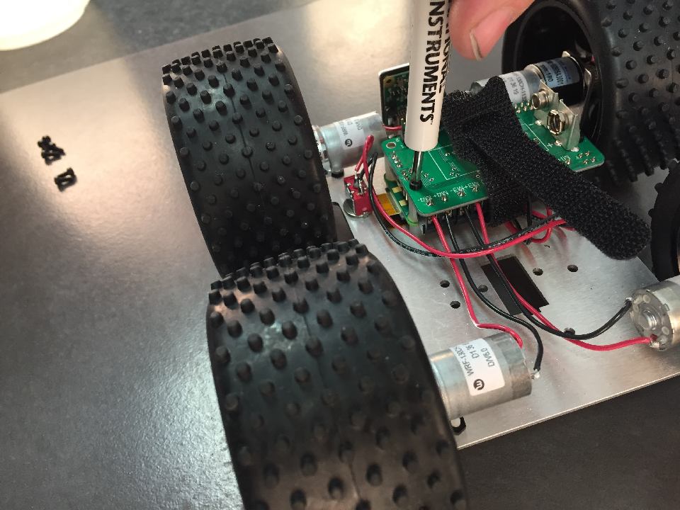
Screw in the ZeroBorg. Make sure the 6 pins locate from ZeroBorg to Raspberry Pi Zero.
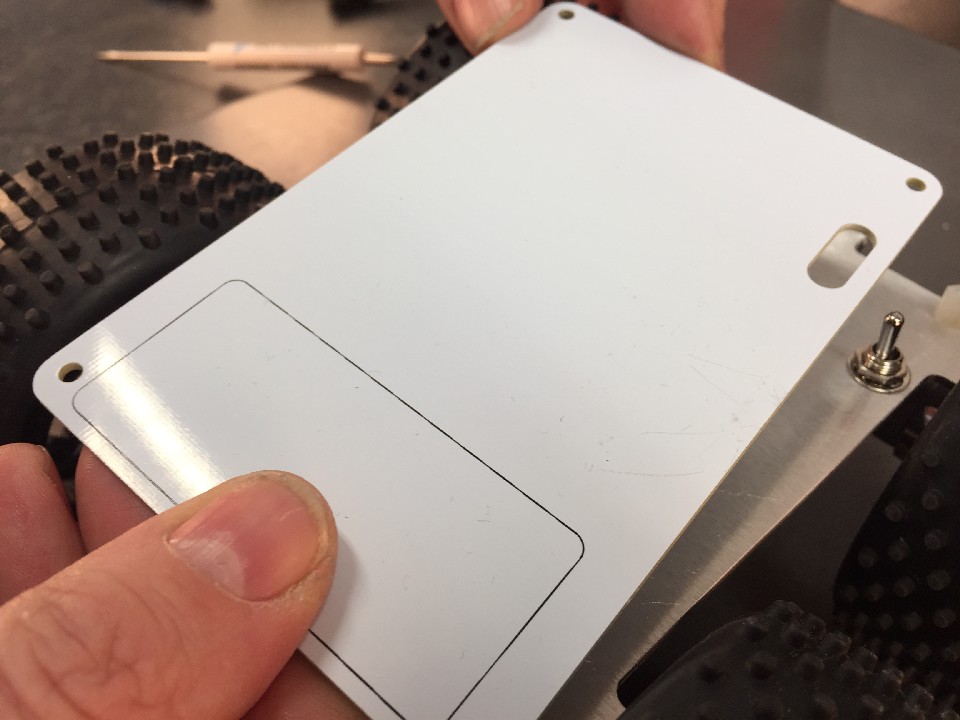
Now it's time to add the YetiLid. Locate the switch cut out and place over it.
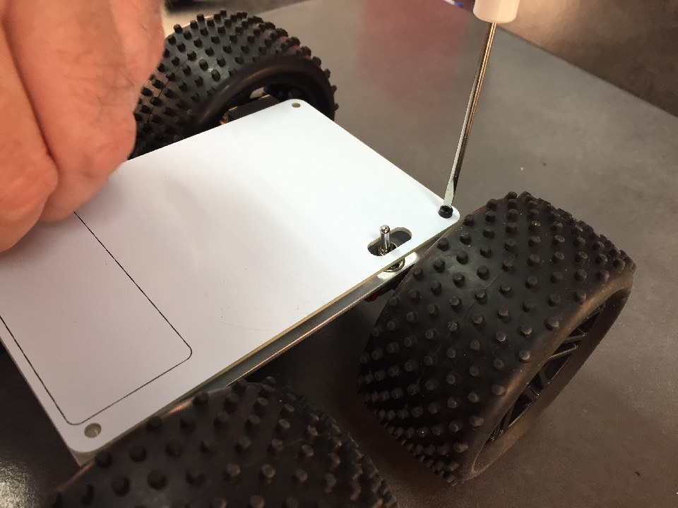
Screw in M2.5 screws x 4
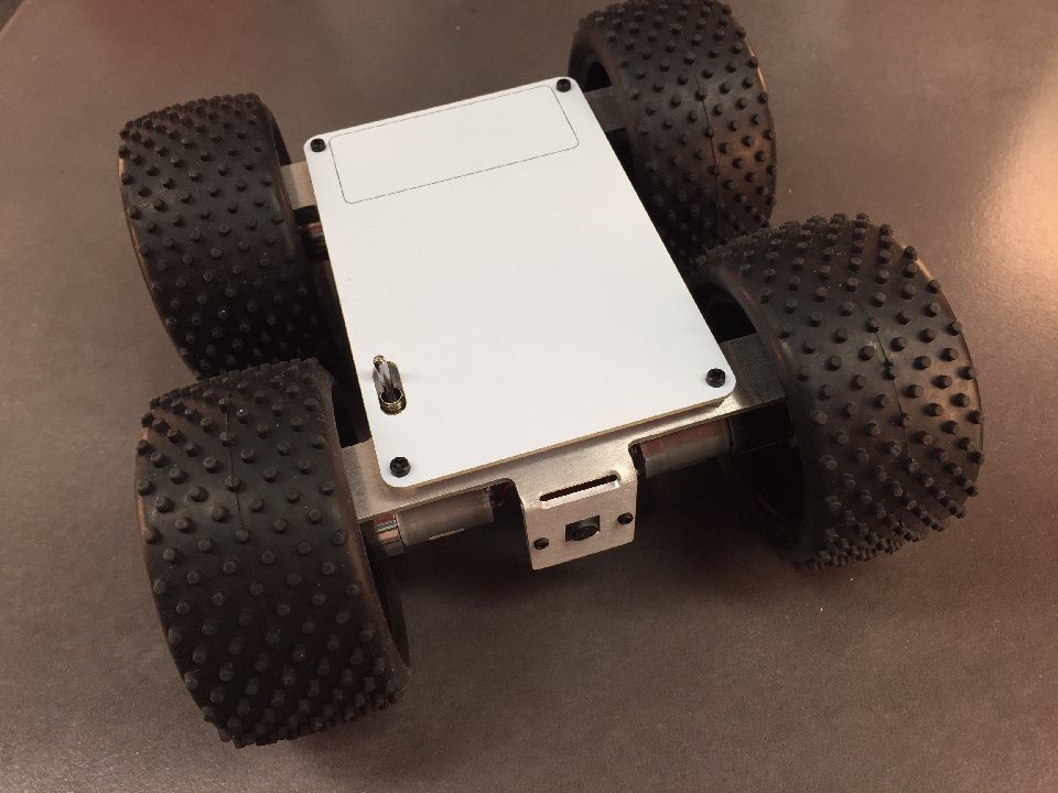
You are now finished. Add battery, software and run! The SD card can be accessed by taking the wheel off.