
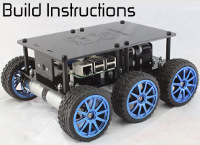
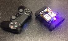
MonsterBorg - The ultimate Pi robot
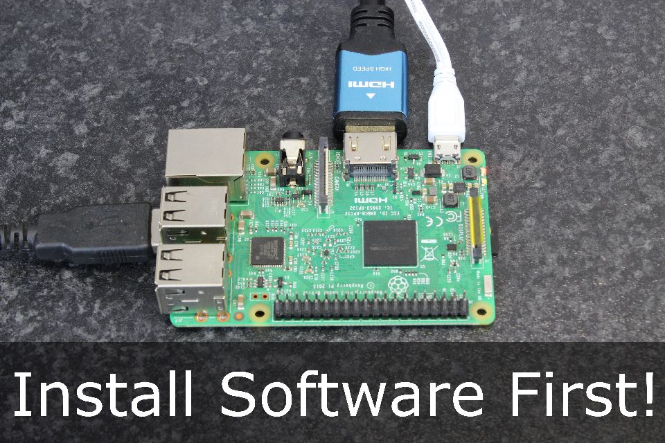
Step 0: Firstly, make sure you have installed the software so you can easily connect and modify code without needing to remove the Raspberry Pi. See the getting started page for more information.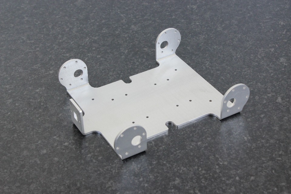
Step 1: Place the chassis on a table with the camera tab oriented the left as pictured.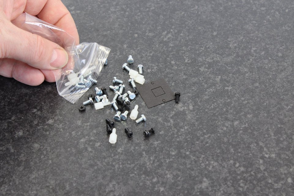
Step 2: Open the bag of screws and check to ensure you have everything.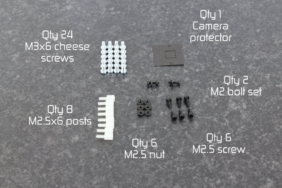
Step 3: The kit should consist of twenty four [M3x6 cheese screws] (top left), eight [M2.5x6 posts], six [M2.5 nuts], six [M2.5x8 nylon screws], two [M2 screws], two [M2 washers], two [M2 posts] and a camera protector.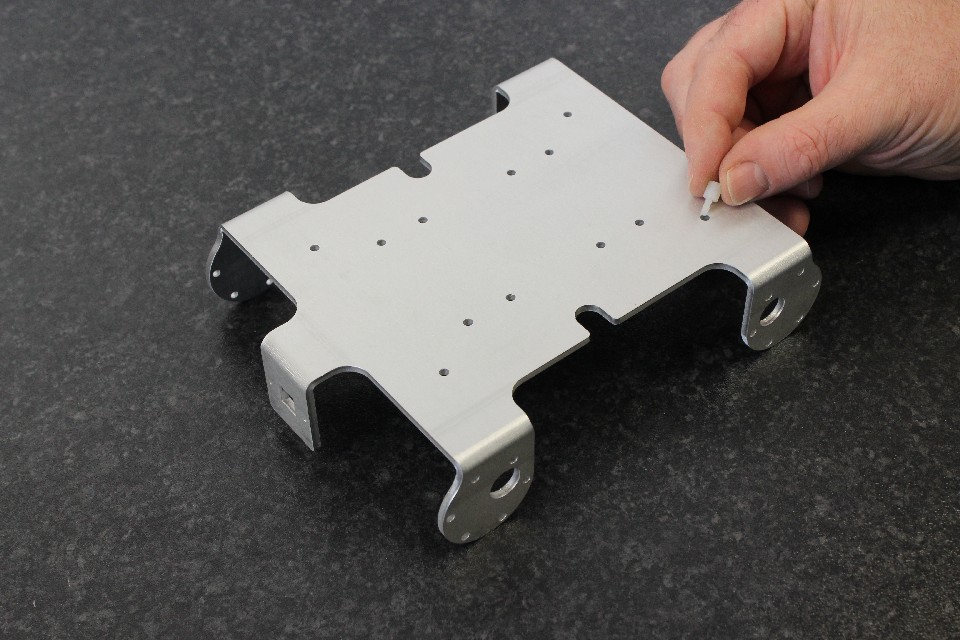
Step 4: Place an [M2.5x6] nylon post in the outer 4 holes of the chassis.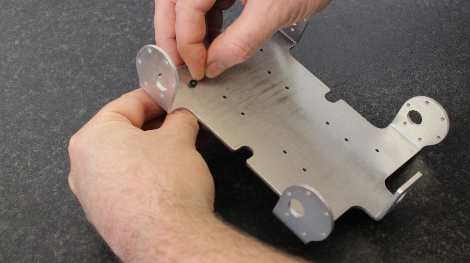
Step 5: Turn the chassis over and place an [M2.5 nylon nut] on the underside.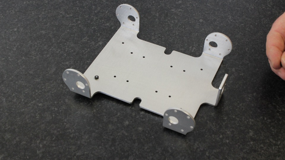
Step 6: These can normally be adequately tightened with fingers or a 5mm socket/socketdriver. Don't over-tighten.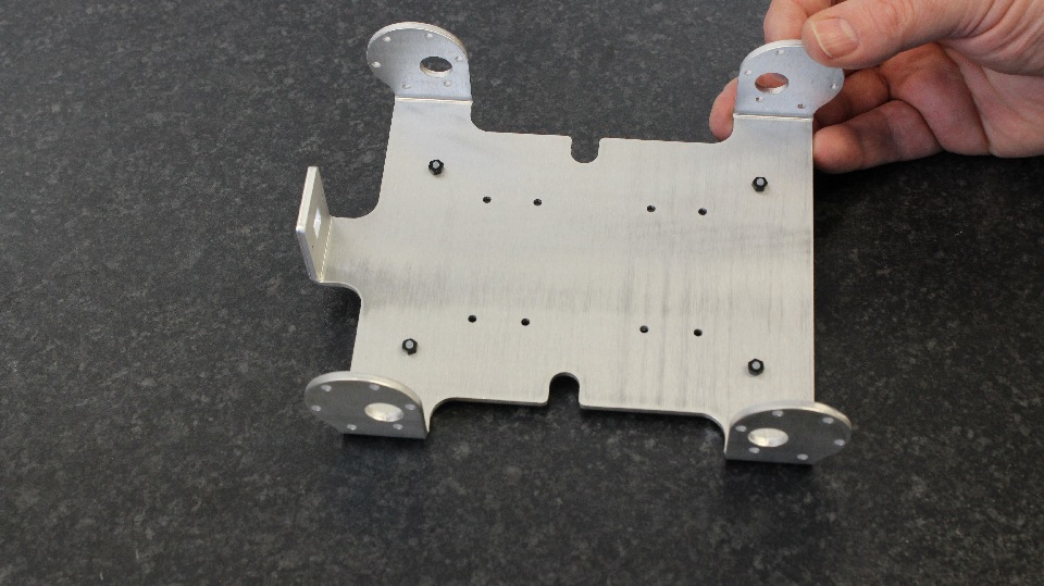
Step 7: Repeat until all 4 outer holes have the post on the top side, and the nut on the underside.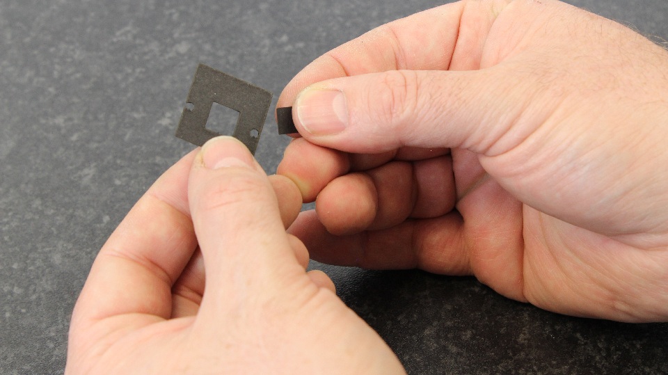
Step 8: Take the camera protector and remove the square tab and two hole tabs. Please note the camera protector can leave black marks so be careful.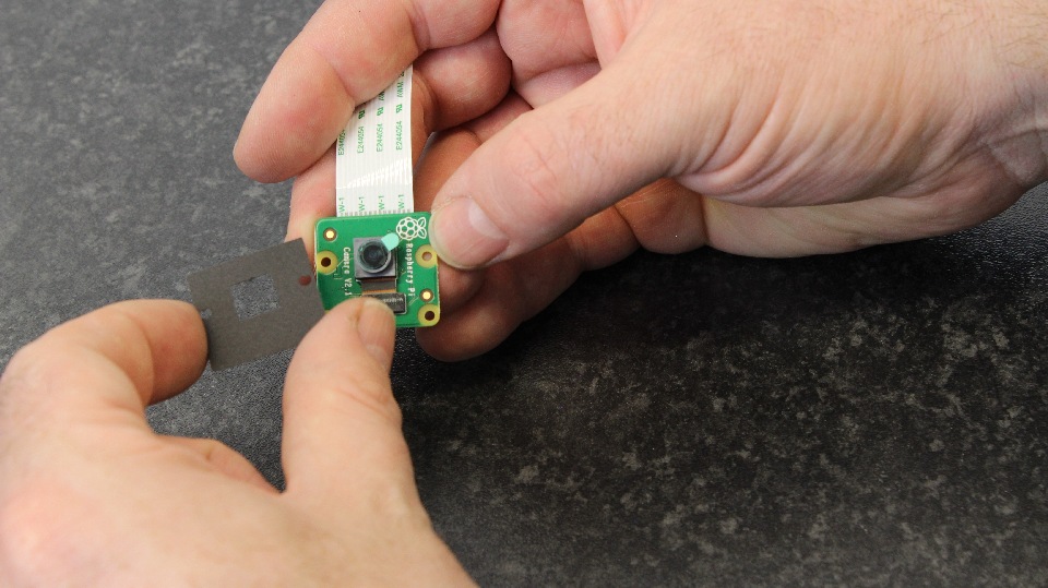
Step 9: Take the Raspberry Pi camera and make sure the camera cable is attached. We will put the protector over it. The Raspberry Pi camera is purchased separately and does not come with the kit.
Step 10: The camera protector should line up like pictured.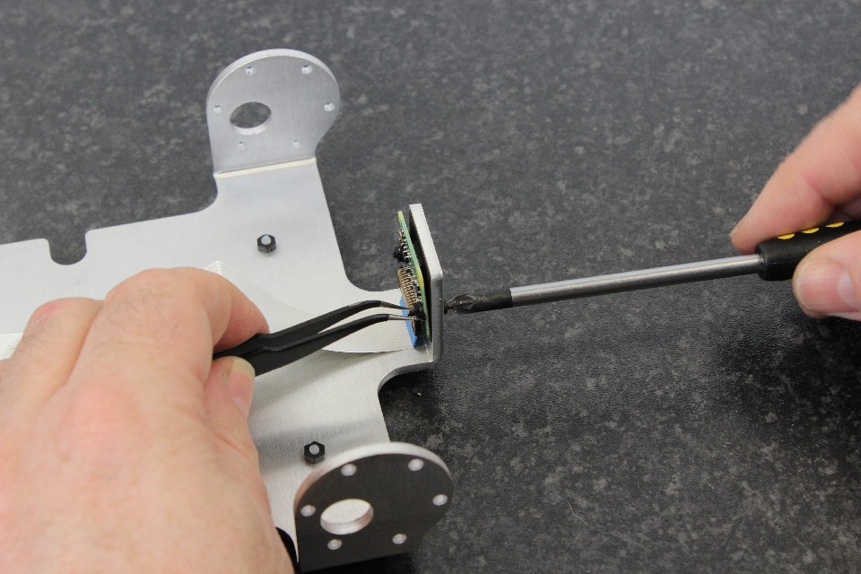
Step 11: Place the camera in the camera slot of the MonsterBorg chassis with the cable oriented towards the chassis. Add the [M2 screw], nut and washer. The screw should come from the front of the robot with the washer and nut behind the camera.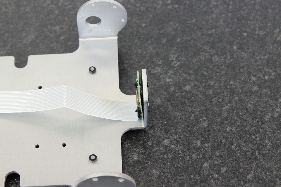
Step 12: This is probably the most difficult part of the assembly of the MonsterBorg. Tweezers might help to hold the tiny nut in place at the back. It might help if you have someone help you do this step!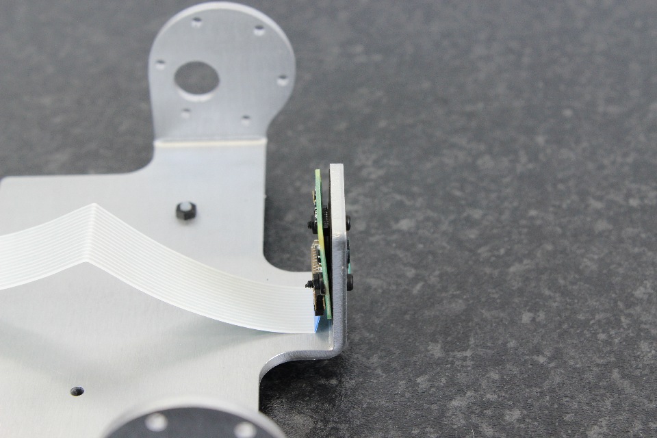
Step 13: A closer picture. The camera should not be loose and the camera PCB should not be bent. Don't over tighten as you can damage the Pi Camera.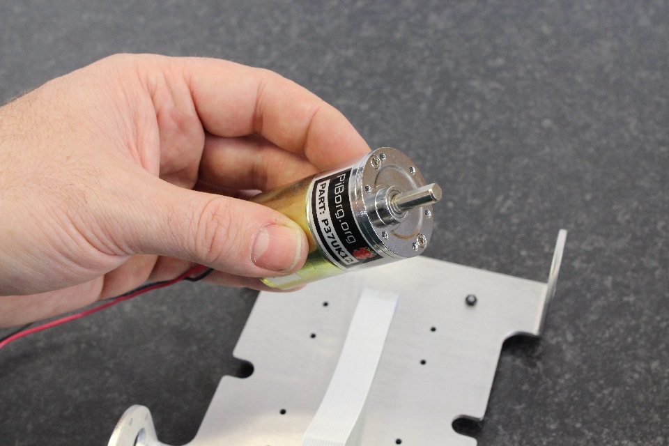
Step 14: Take one of the P37UK12 motors.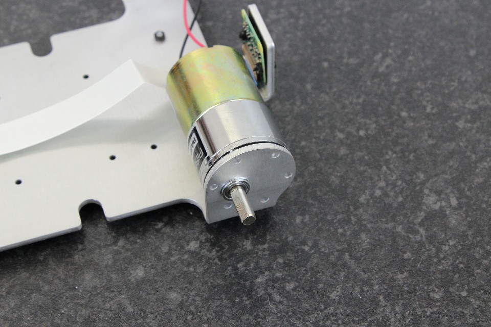
Step 15: Place the shaft through the chassis. It will need to be lined up straight to slot in.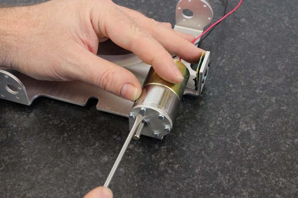
Step 16: Add the [M3x6 screws]. To get the first one in, rotate the motor until the holes in the motor line up with the chassis. Add all 6 screws by hand before tightening any.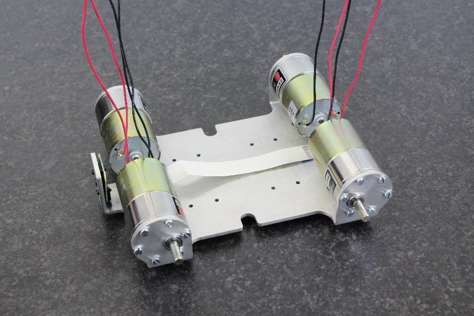
Step 17: Tighten the screws and repeat for all 4 motors.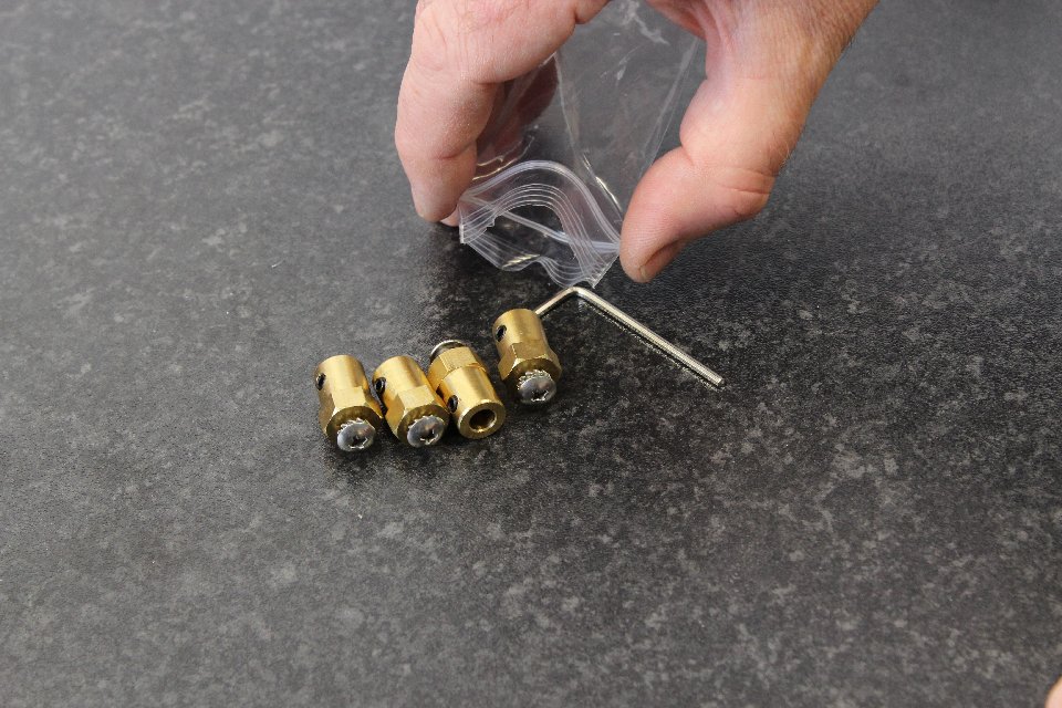
Step 18: Empty the bag with the 4 hubs and allen key.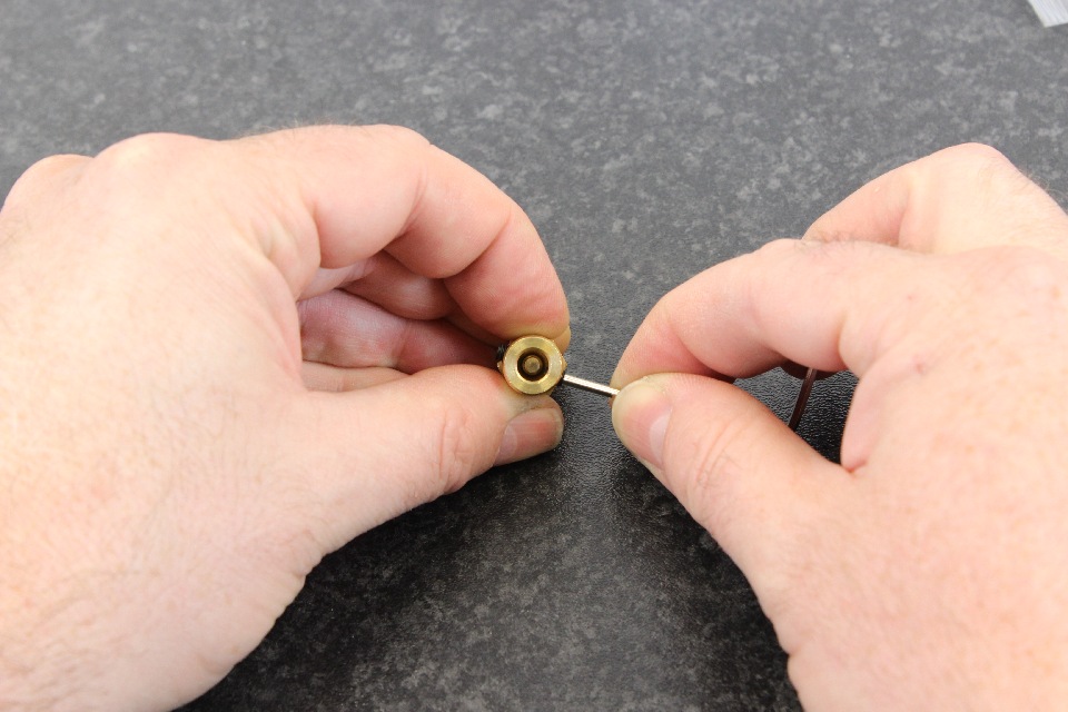
Step 19: Unscrew the grub screws so that they do not protrude into the hole. Also loosen the Phillips (cross) screw a small amount.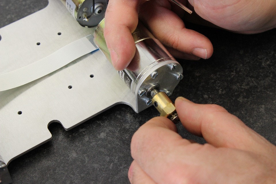
Step 20: The hub should slot over the motor. If it does not, loosen the grub screws. Orient the hub so that the grub screw and the slot in the motor shaft line up.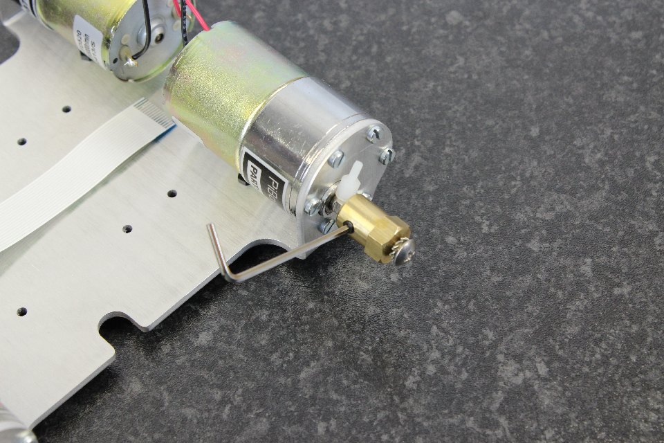
Step 21: Make sure that the allen key is properly located in the grub screw before tightening, then tighten the grub screw that is aligned with the shaft. Use one of the [M2.5x6 nylon posts] to get the correct distance from the motor. If it won't go on far enough, be sure to loosen the Phillips (cross) screw.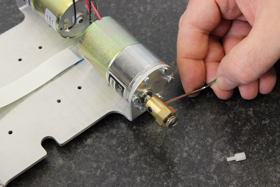
Step 22: Tighten the other side grub screw. Again, make sure that the allen key is properly located in the grub screw before tightening. Then tighten the first one again. Both should be quite tight but be careful not to overtighten. (Leveraging from the long end of the Allen key, the amount of force needed is about the same as opening a bottle of Coca-Cola).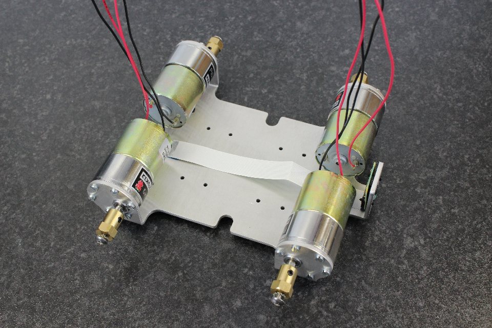
Step 23: Repeat the process for all 4 hubs.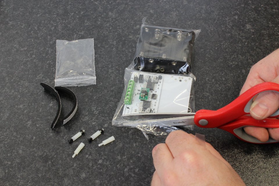
Step 24: Open the bag with the ThunderBorg motor controller. In here are two [M2.5x12 posts] with a screw and nut each, and two pairs of posts (these are actually made up of a [M2.5x8 post] and a [M2.5x6 post].)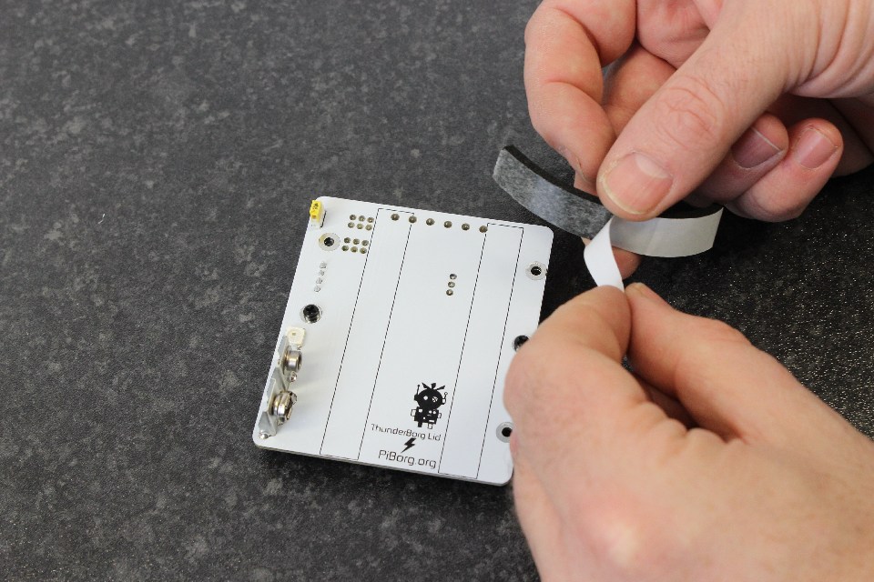
Step 25: Take the two rubber strips and peel back the protective layer.
Step 26: Stick this in the marked place on the ThunderBorg lid.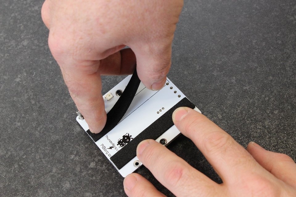
Step 27: Repeat for the other side.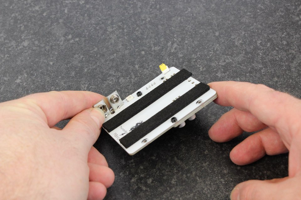
Step 28: The two strips will form the layer that the batteries rest on.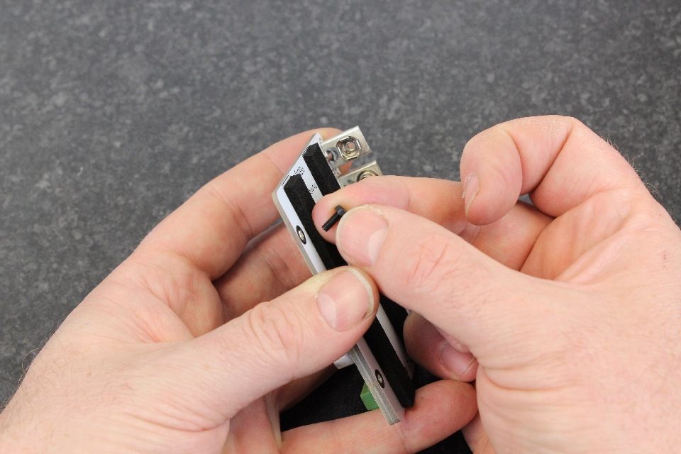
Step 29: Take a [M2.5x8 nylon screw] from the first kit you opened, and place it in one of the bottom holes of the ThunderBorg lid. The bottom holes are the ones next to the silver connectors and opposite.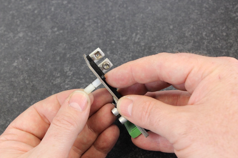
Step 30: From the second kit you opened, take the [M2.5x6 post] and [M2.5.x8 post] pair and tighten on the screw.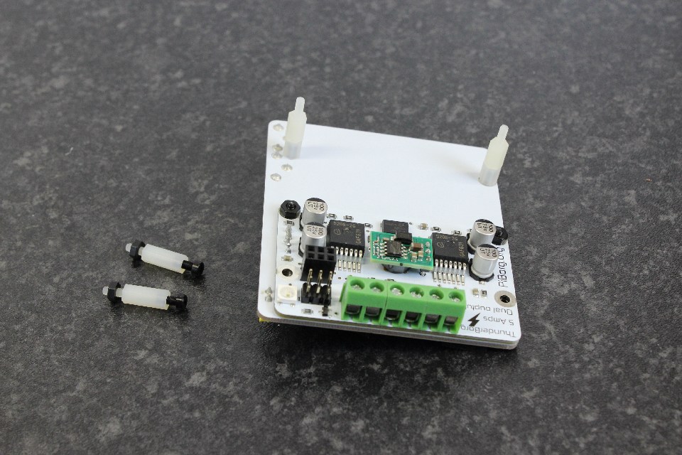
Step 31: Repeat this for the other bottom hole. It should look like the picture. Notice the single length posts aren't used yet, and the post pair are such that the small one (M2.5x6) is at the bottom, the larger one (M2.5x8) is at the top.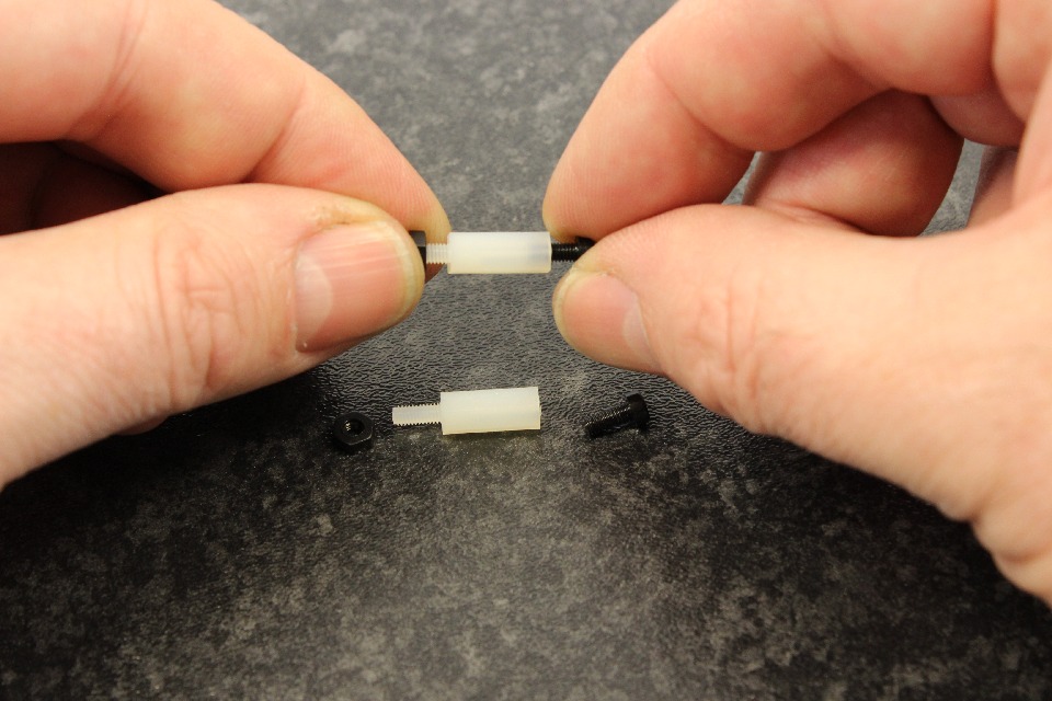
Step 32: Now unscrew the screws and nuts off the [M2.5x12 posts].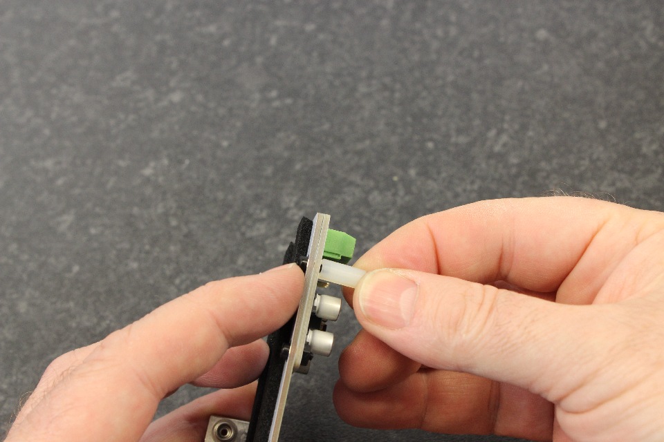
Step 33: Add the [M2.5x8 screw] and place an [M2.5x12 post] on the motor controller side.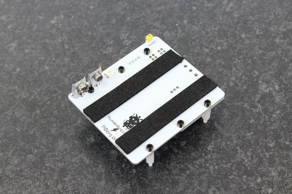
Step 34: The screw should go through from the rubber strip side and the post should be on the ThunderBorg side.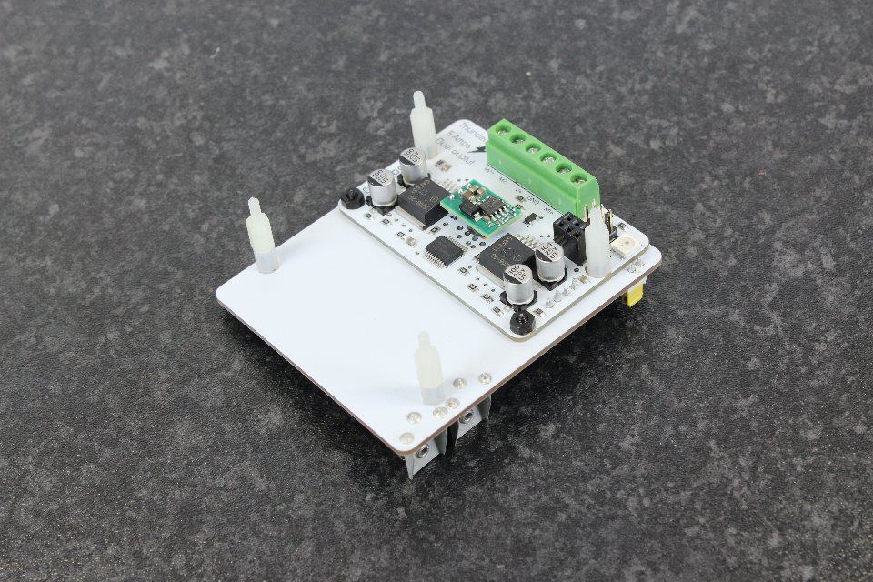
Step 35: The ThunderBorg Lid and ThunderBorg should look like the picture.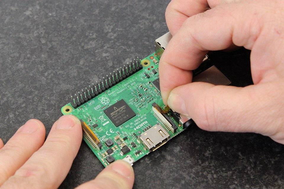
Step 36: Take the Raspberry Pi (Purchased separately and not part of the kit) and peel off the adhesive plastic on the camera connector.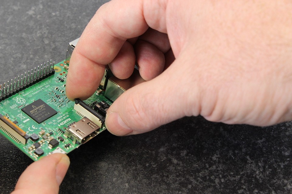
Step 37: Very gently lift the top (black part) from the two tabs. It will only come up a small amount, it does not come off.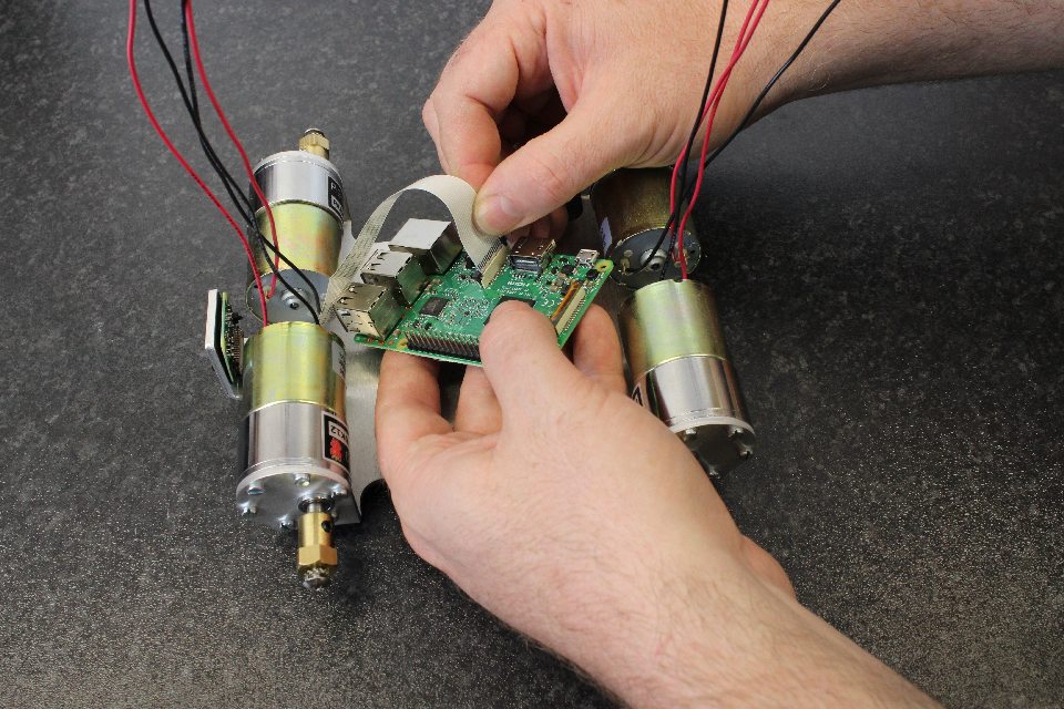
Step 38: Place the camera cable in the slot, so that the blue part is directed towards the USB and network sockets, and the silver connectors are directed towards th HDMI connector.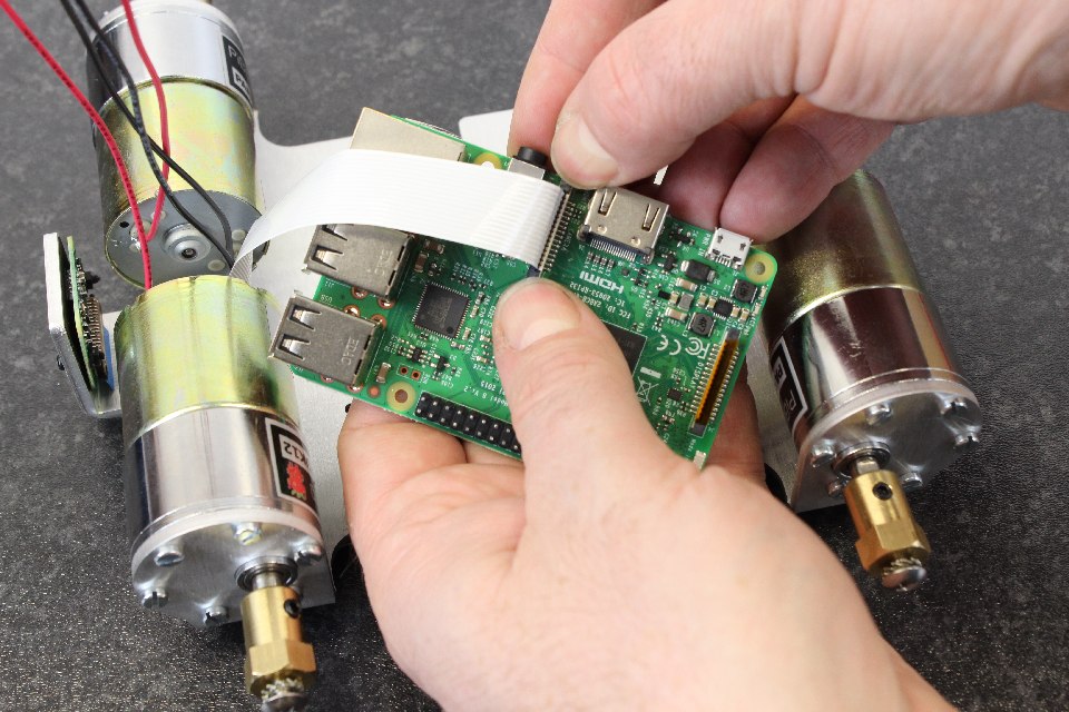
Step 39: Make sure the cable is oriented so that it is straight with the connector. With a gentle push on the cable it should side in to the connector. When correctly in place, the silver connectors are just slightly above the level of the top of the connector (the white part of the connector).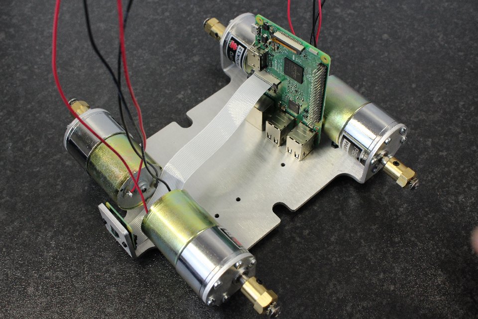
Step 40: It should look like this picture.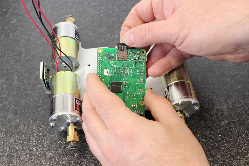
Step 41: Place the SD card with the code from step zero. It should have the connectors towards the Pi as pictured.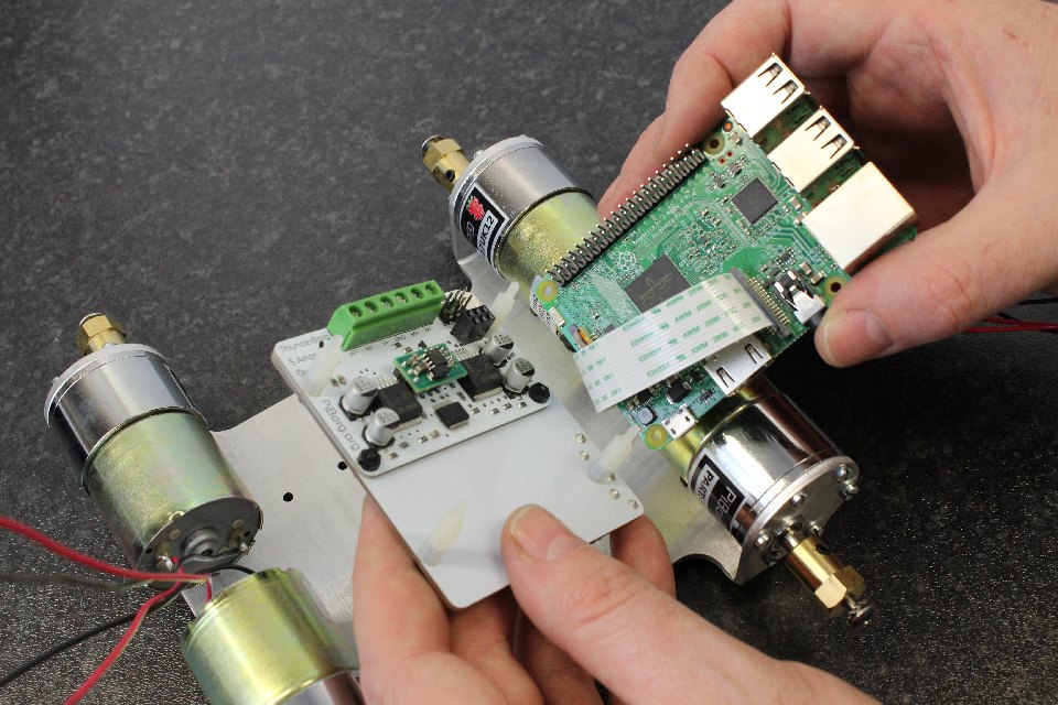
Step 42: Take the ThunderBorg and ThunderBorg lid, and connect them together. The first 6 GPIO pins of the Raspberry Pi should line up with the female 6 pin header on the ThunderBorg as pictured. Be careful not to pinch the camera cable.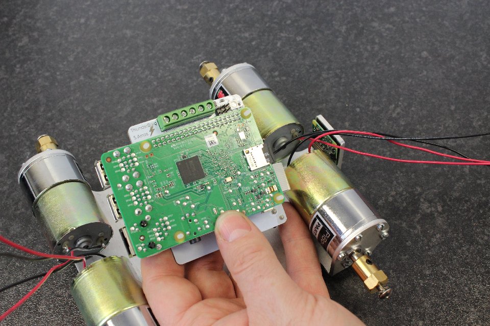
Step 43: The screw threads of the posts should locate through the Raspberry Pi holes.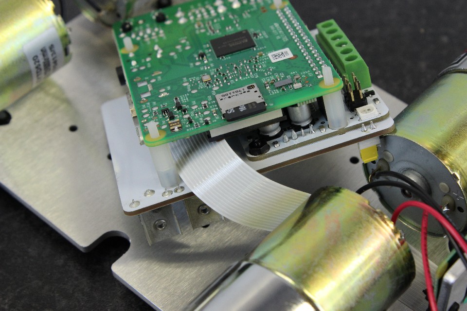
Step 44: Check the camera cable is not pinched, and the 6 pins on the Raspberry Pi are in the female header.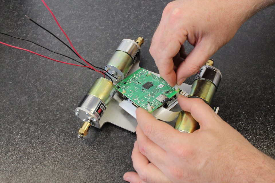
Step 45: Screw the remaining [M2.5x6 posts] on to the protruding post threads.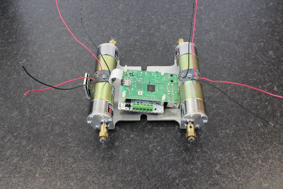
Step 46: Repeat for all 4 posts.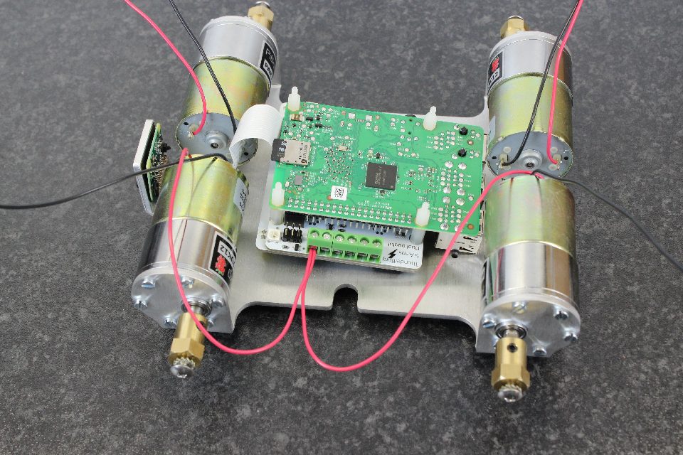
Step 47: Make sure the chassis is oriented as shown. That is, camera to the left. Take the two red wires from the two motors closest to you. Place the ends of the wire in the connector on the far left.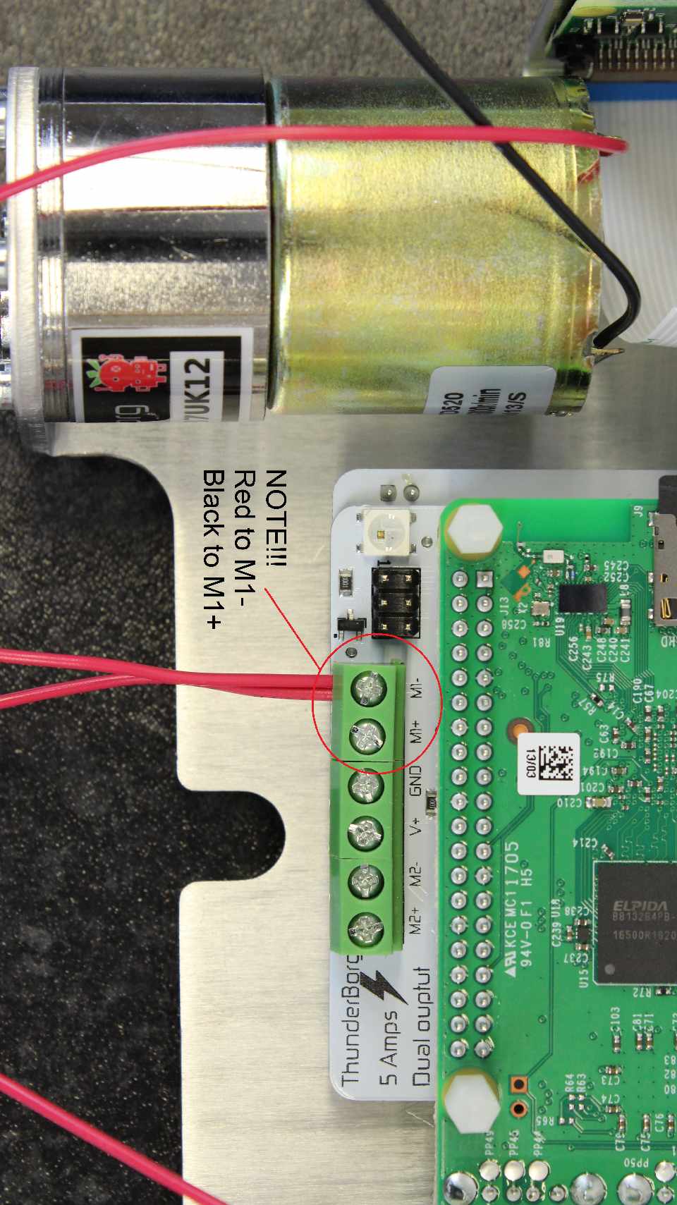
Step 48: The motors on this side are inverted in direction, so we want to connect the Red to M1-. It's not a mistake :)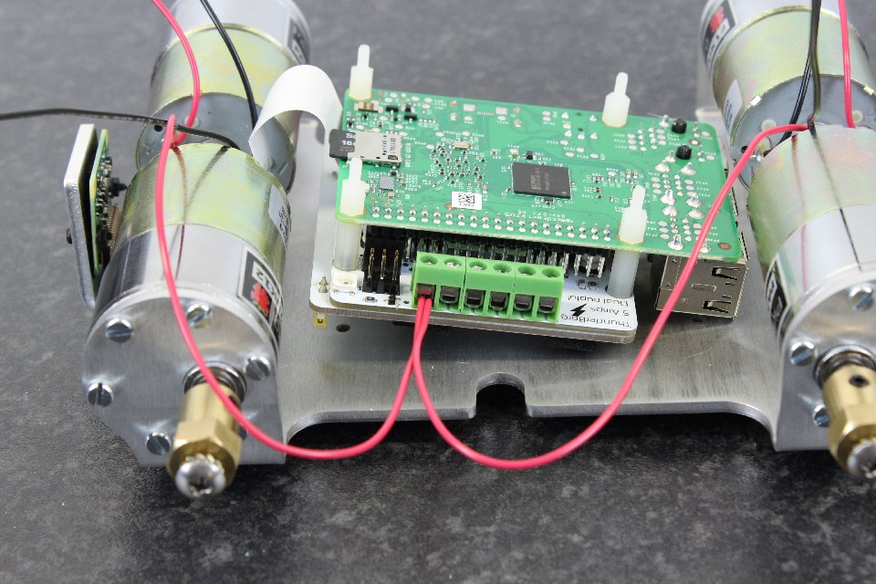
Step 49: Make sure that the wires are between the clamp and tighten. It is possible to locate the wire underneath the clamp, so double check it has grabbed both wires by the metal conductor.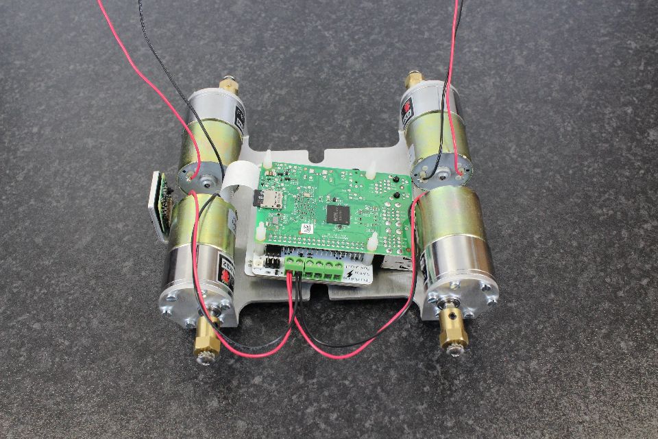
Step 50: Connect the two black wires from the motors closest to you to the next connector along (M1+) and tighten.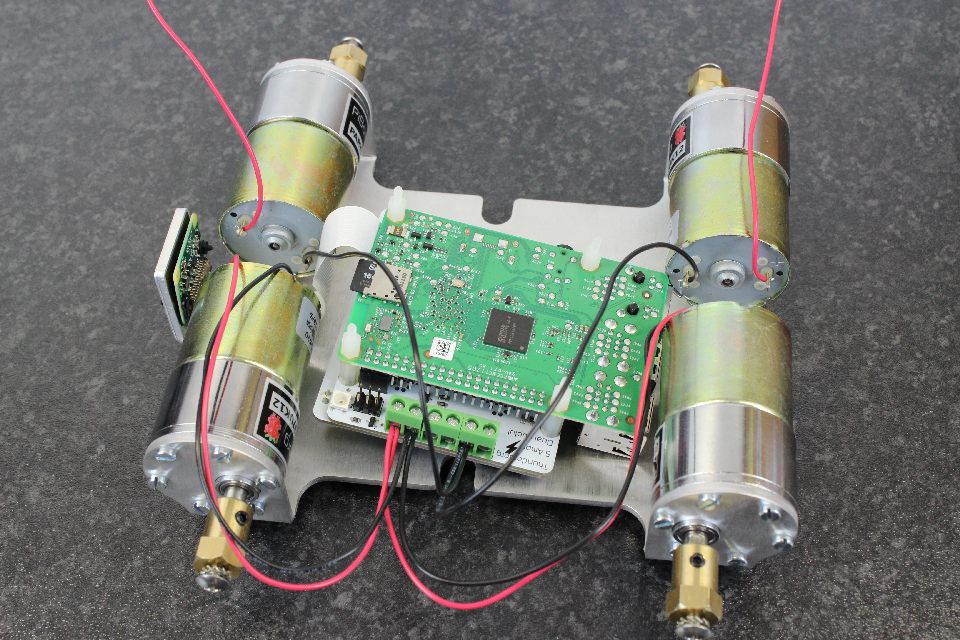
Step 51: Put the two black wires from the top two motors into the second last connector (M2-) and tighten.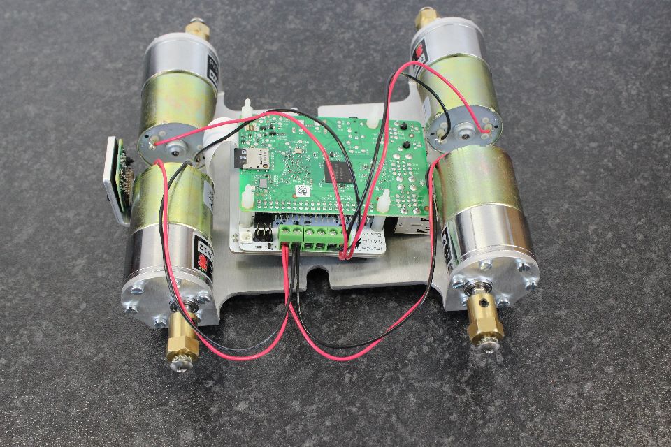
Step 52: Put the two red connectors from the top two motors into the last connector (M2+) and tighten.
Double check connections and *gently* pull on the wires to see if they are all gripped well.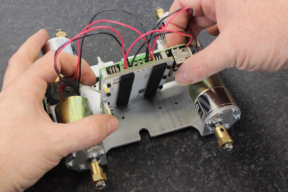
Step 53: Turn the board over carefully while making sure the camera cable doesn't get caught on the motors.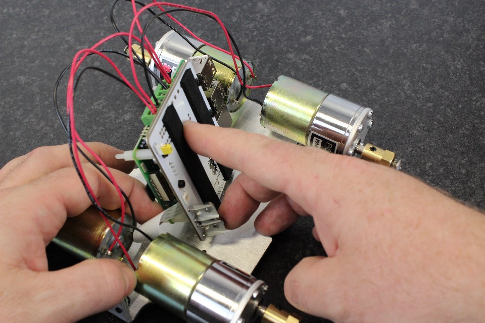
Step 54: The camera cable can easily get snagged at this stage, so turn it over slowly and carefully.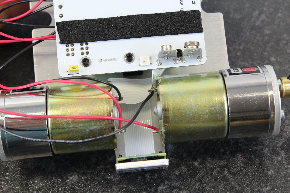
Step 55: The camera cable can be very squeezed so that it stays in place. Do not fold tightly as you could break the connectors inside. The orientation of the cable in the picture works well.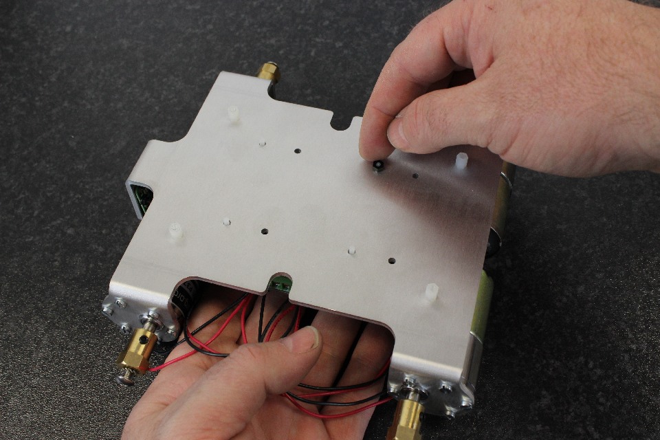
Step 56: Whilst holding the chassis and the ThunderBorg and ThunderBorg Lid, turn over carefully and align the posts so that you can put the M2.5 nuts on the threads.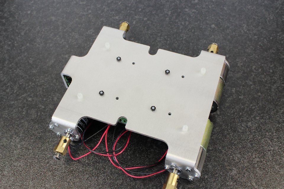
Step 57: Tighten the [M2.5 nuts].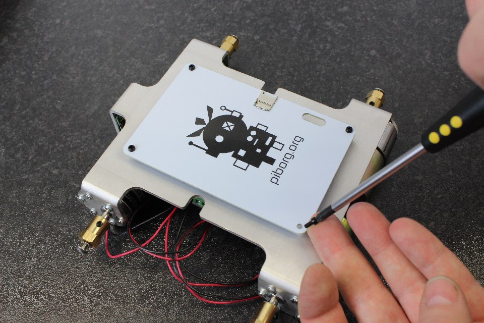
Step 58: Take the Yeti Lid and place on top of the 4 posts. Put four [M2.5x8 nylon screws] in the Yeti Lid. The Yeti Lid can be oriented with the PiBorg logo outside or inside.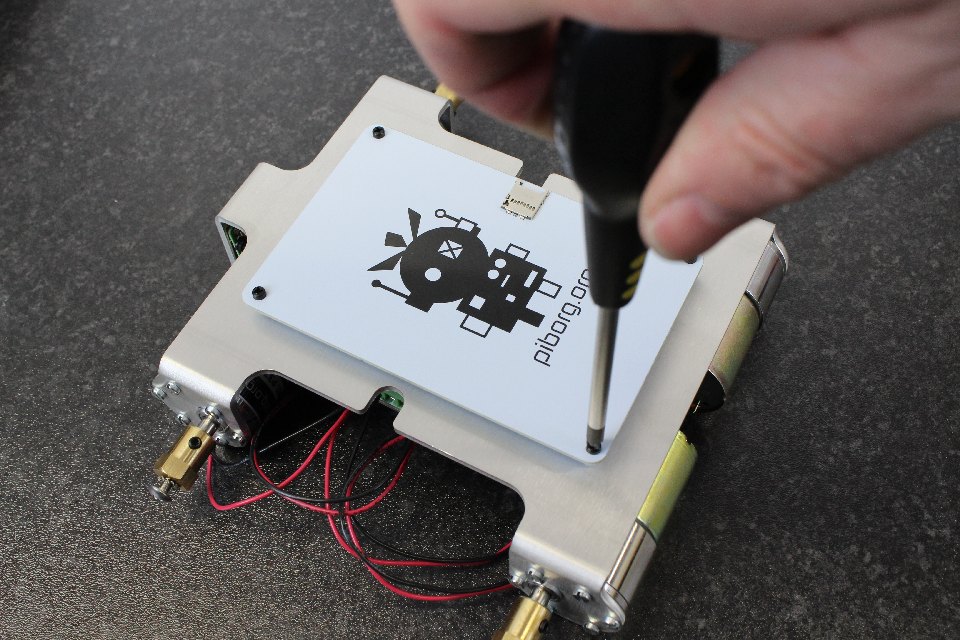
Step 59: The SD card slot in the lid is for convenience of keeping additional SD cards, and is useful for sending us an SD card with your decorated lid if you join Formula Pi. If you do decorate your lid for Formula Pi, don't decorate in the box, as that is where your race numbers will go.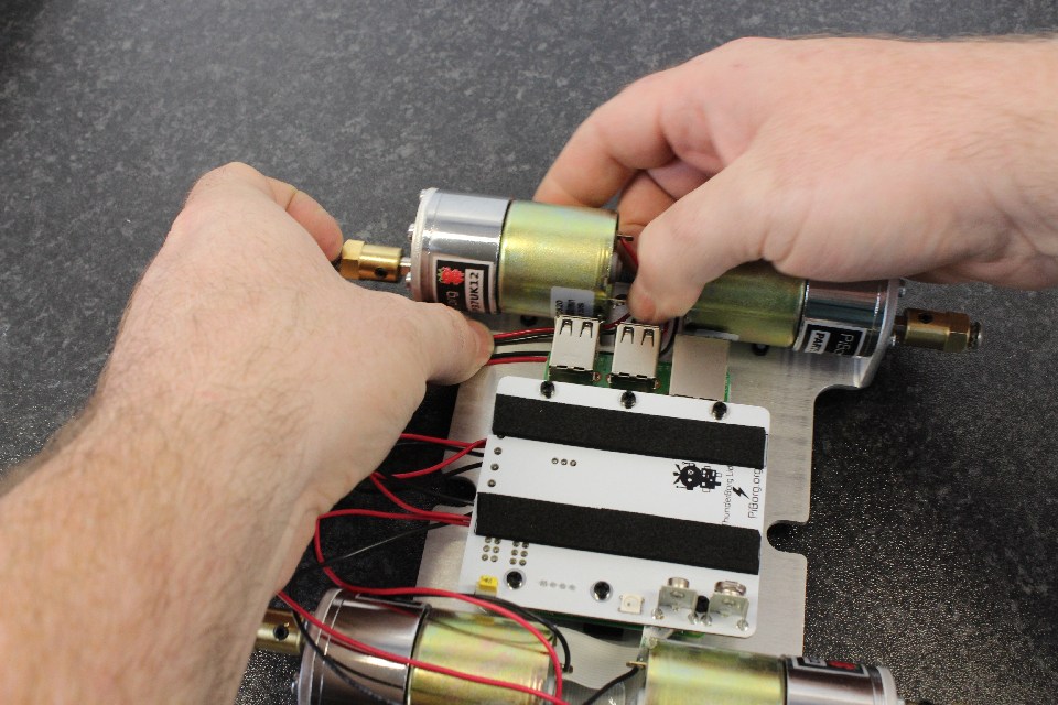
Step 60: Gently push the wires down and out of the way. This is so you can carefully get to the bottom USB slot to plug in a keyboard or USB hub.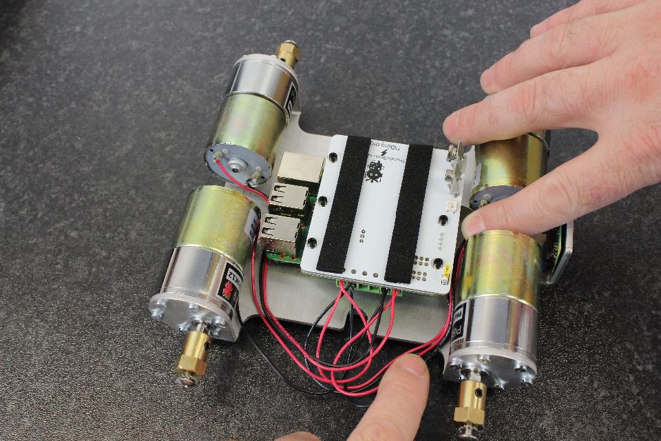
Step 61: Gently push the wires down and around the front so that they don't get caught on anything.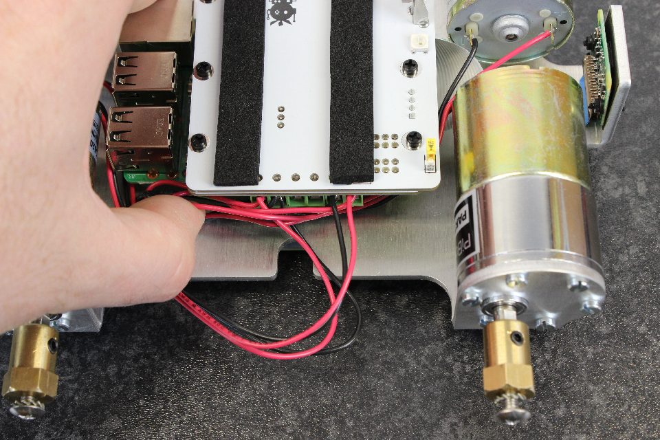
Step 62: The wires can be pushed to the side and underneath as shown (the front motors to the left, the rear motors to the right).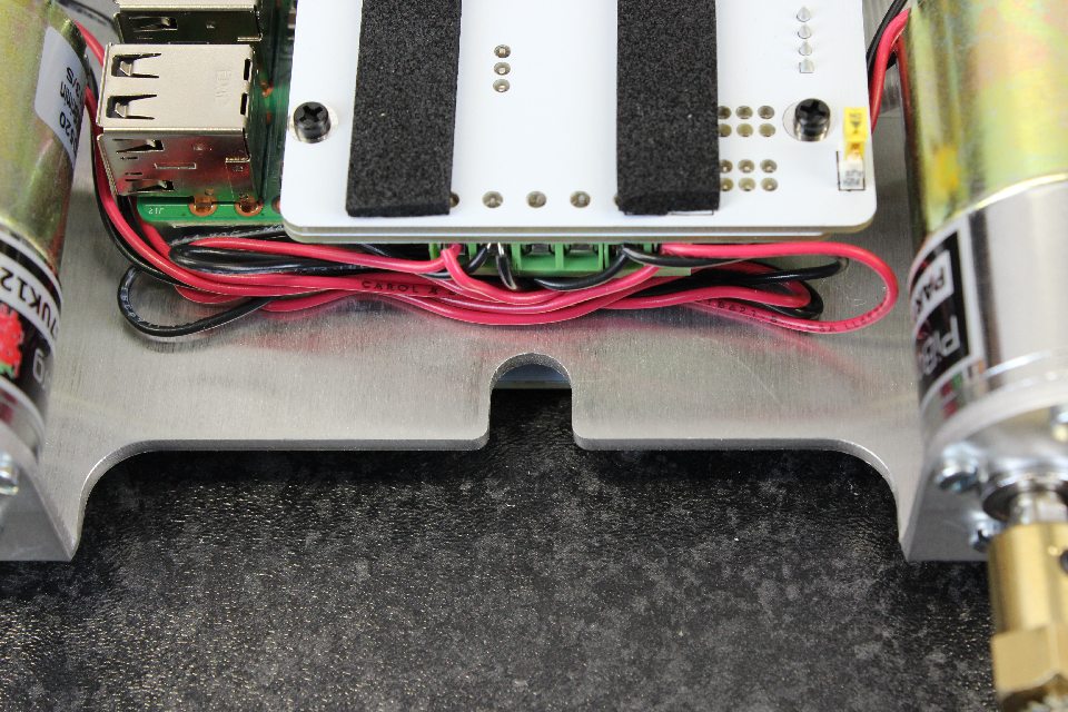
Step 63: Make sure the wires aren't in the way of the slot on the chassis as this is where our battery holder strap will go.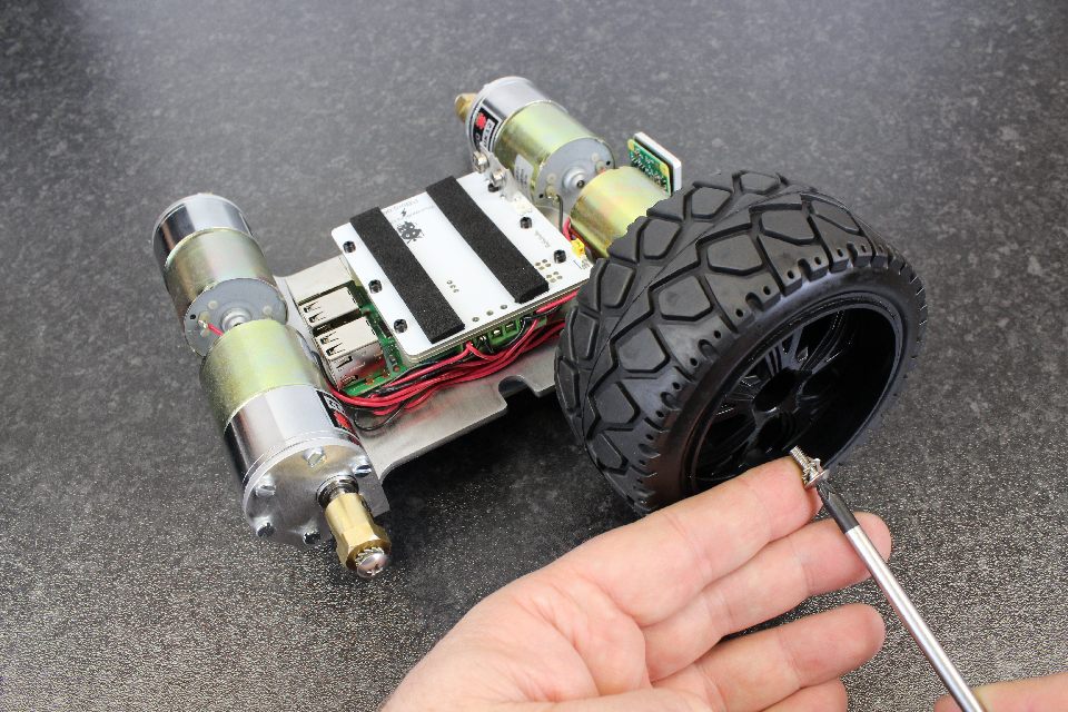
Step 64: Remove the screw and shakeproof washer from the hub. Take a wheel and put it on the hex pattern of the hub. Screw in tightly.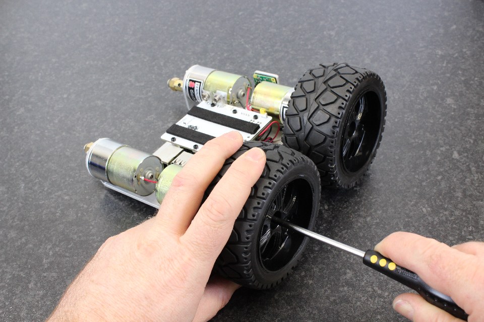
Step 65: Repeat for the other wheels.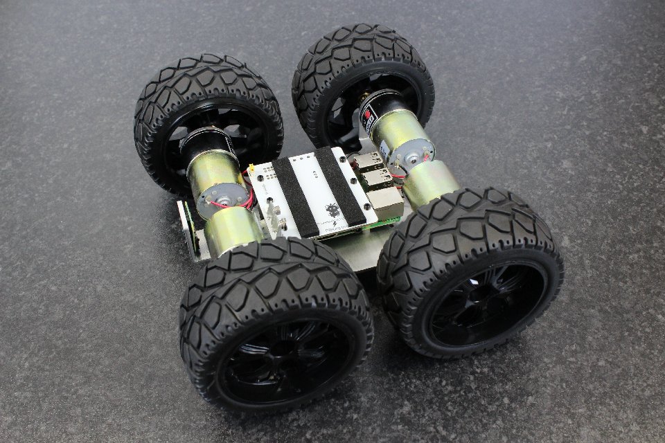
Step 66: Your MonsterBorg should be taking shape! It's not far now.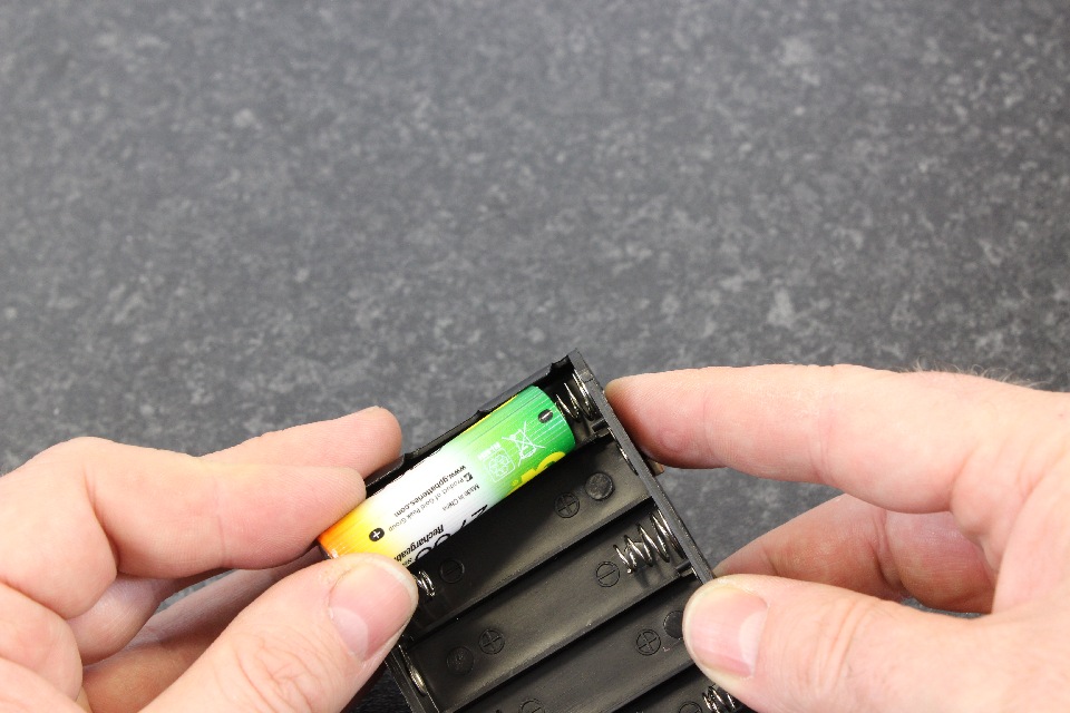
Step 67: Take the battery holder and put in 10x AA batteries (batteries purchased separately and are not part of the kit). Make sure the batteries are correctly orientated. That is the negative to the spring.
Make sure they are charged.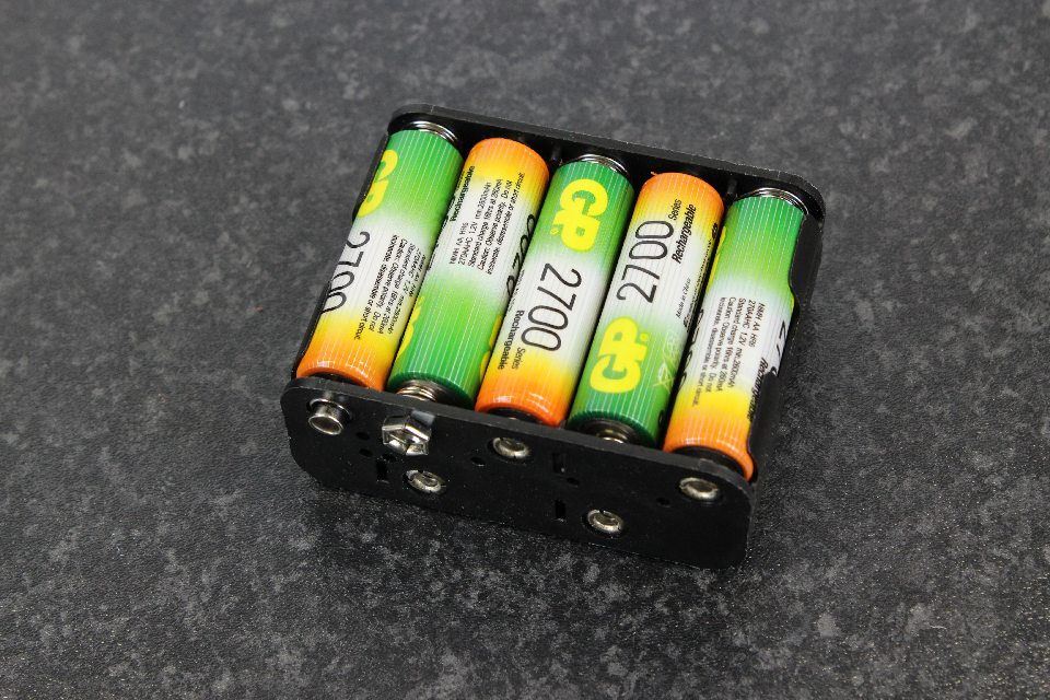
Step 68: We have been using GP2500/2600/2700 and they work quite well. A quick way to check you have the polarity of the batteries right is that the green on the GP's are next to the spring, and that the pattern of Green/orange goes around the whole battery pack.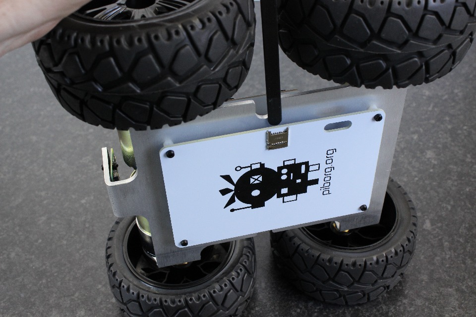
Step 69: Take the re-usable cable tie and put it between the YetiLid and the chassis.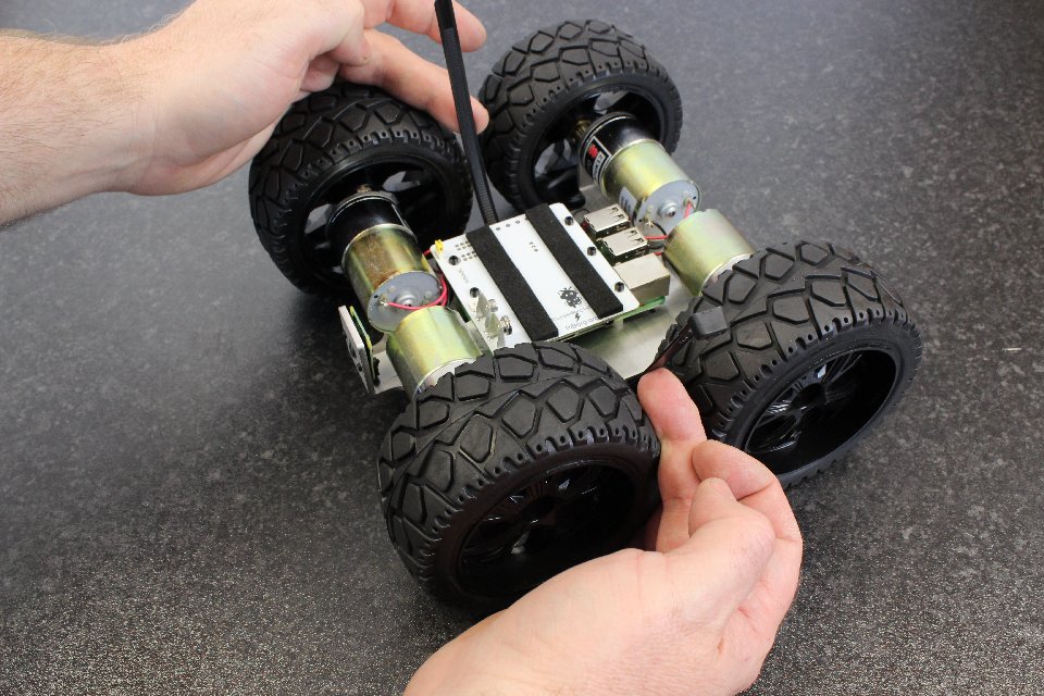
Step 70: The cable tie should be oriented so that the head is on the robot side, and that it points away from the center of the robot.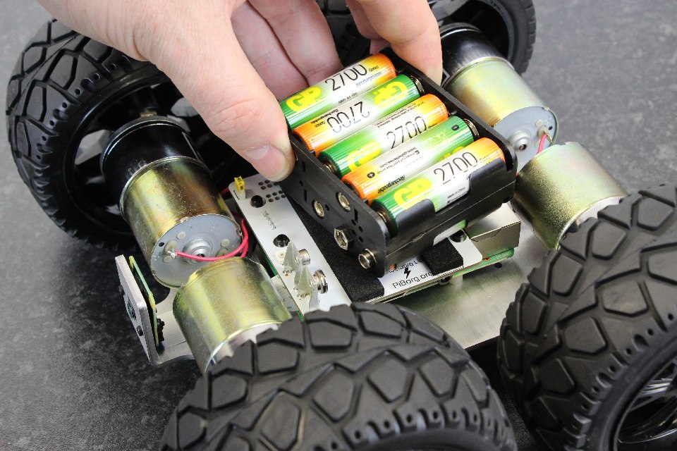
Step 71: Make sure the switch (yellow) is in the off position. Be gentle with the switch as it really doesn't take much force to switch on and off! Carefully connect the battery pack to the ThunderBorg Lid.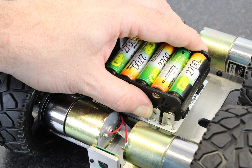
Step 72: When correctly aligned and tight, slide the end part of the cable tie between the battery pack and the ThunderBorg lid.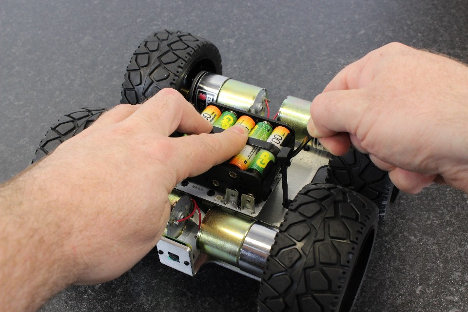
Step 73: Tighten the cable tie by holding the battery pack and top of the strap with your fingers.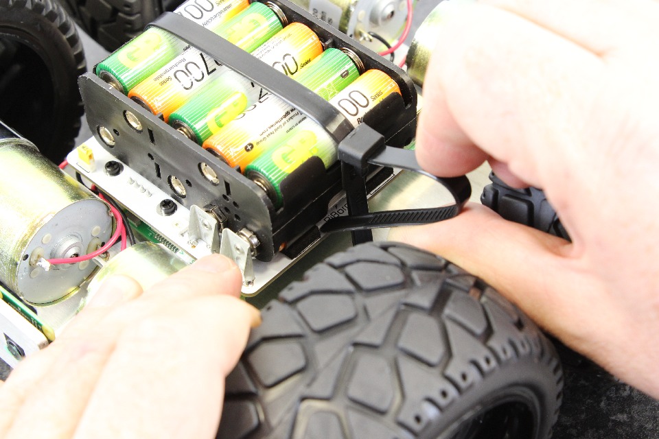
Step 74: Tuck the excess end of the cable underneath the battery pack.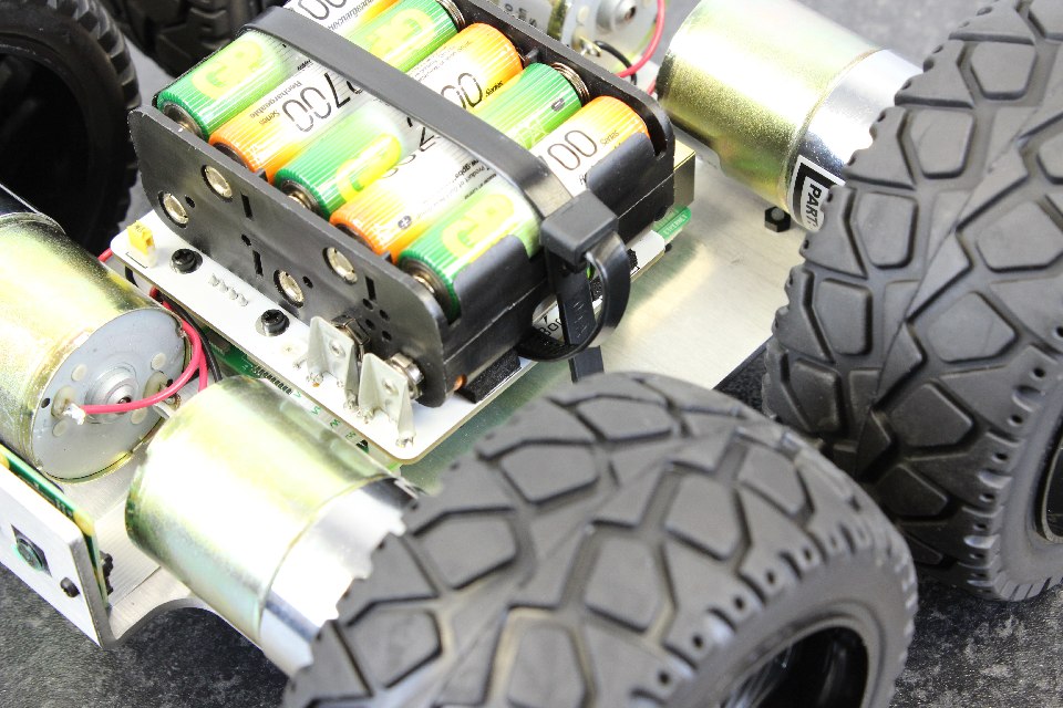
Step 75: Here is a picture of the cable tie correctly tight and secure.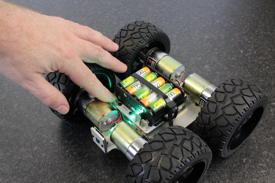
Step 76: Now you can switch the switch over to ON! The LED sequence on the ThunderBorg should go through Red, green and blue, and then it should go to voltage monitoring. Depending on your voltage monitoring setup, it should display the voltage on your battery pack. That is essentially green for charged, and red/orange for flat.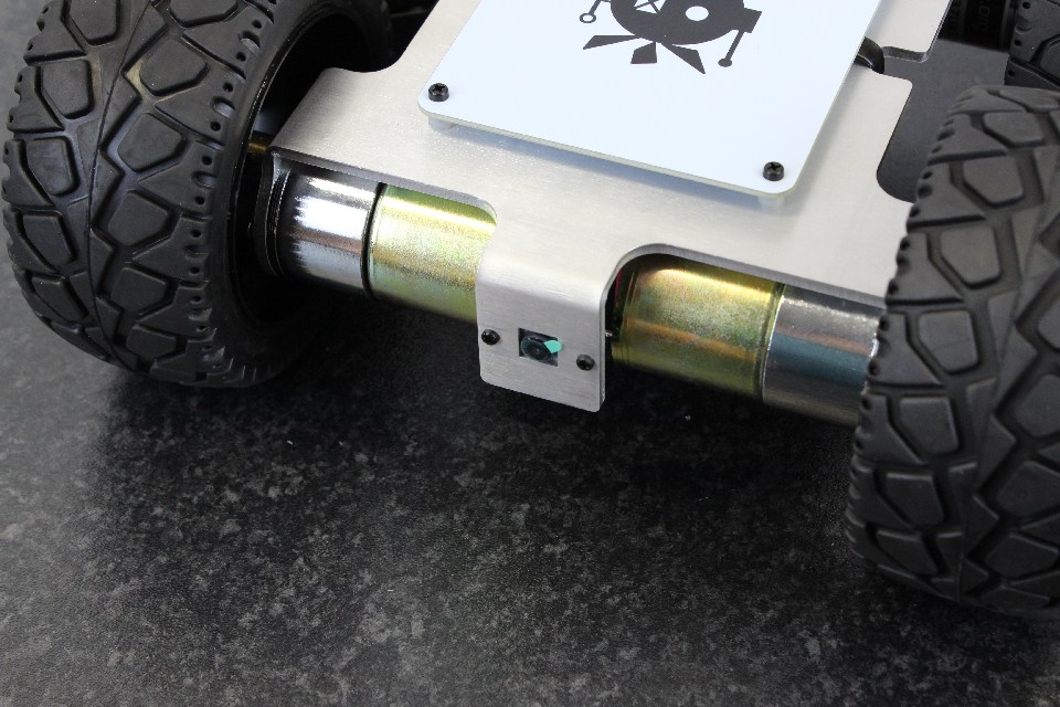
Step 77: If it's still on, don't forget to remove the lens protector on the Raspberry Pi camera.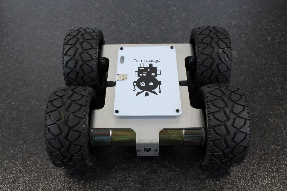
We're all done! Here are some pictures of the finished MonsterBorg. From the front...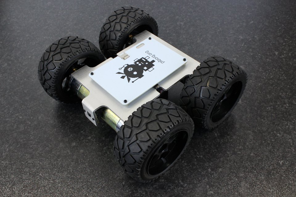
From the side...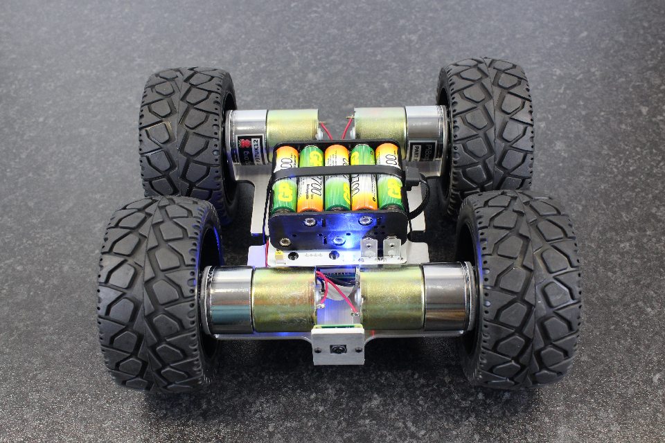
From underneath...
Now that we're all ready to go, you can try some of the examples.
![[M3x6 cheese screws]](/images/monsterborg/build/Step_3-1440.jpg)