ZeroBorg - Tiny robot controller for your RPi Zero based robots
Installation
Mounting
Two basic mounting options are provided:The first option is to mount the ZeroBorg underneath of a Raspberry Pi Zero using the four mounting posts to hold the Raspberry Pi Zero in place.
This will need a 6-pin female connector to be attached to the Raspberry Pi Zero like this:
alternatively if you would rather not solder the 6-pin connector you can try a temporary connection:
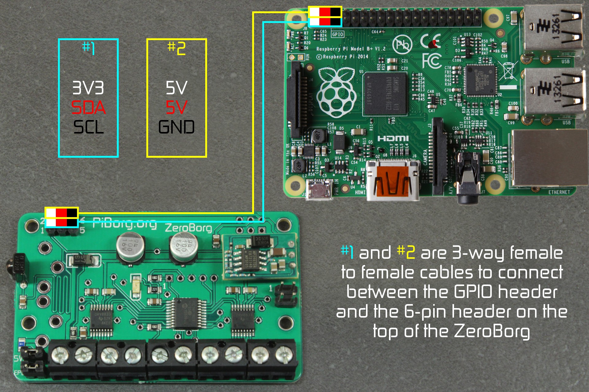
The second option is to use two 3-pin female-female cables to connect the ZeroBorg to any version of the Raspberry Pi.
This will allow you to mount the ZeroBorg using any combination of the four available mounting holes to part of the robot you are building, we recommend using all four if possible.
The outlines in the image below show an individual 3x1 pin cable (not supplied), the coloured boxes show the colour of the wire.
If stacking multiple ZeroBorgs only the top board is directly connected to the Raspberry Pi.
Each ZeroBorg will need to have the pin connections swapped over, this is already done in the ZeroBorg KS3 - stack of three ZeroBorgs.
You can also connect other boards to the spare 6-pin header on the bottom of the ZeroBorg if they only need I2C connections.
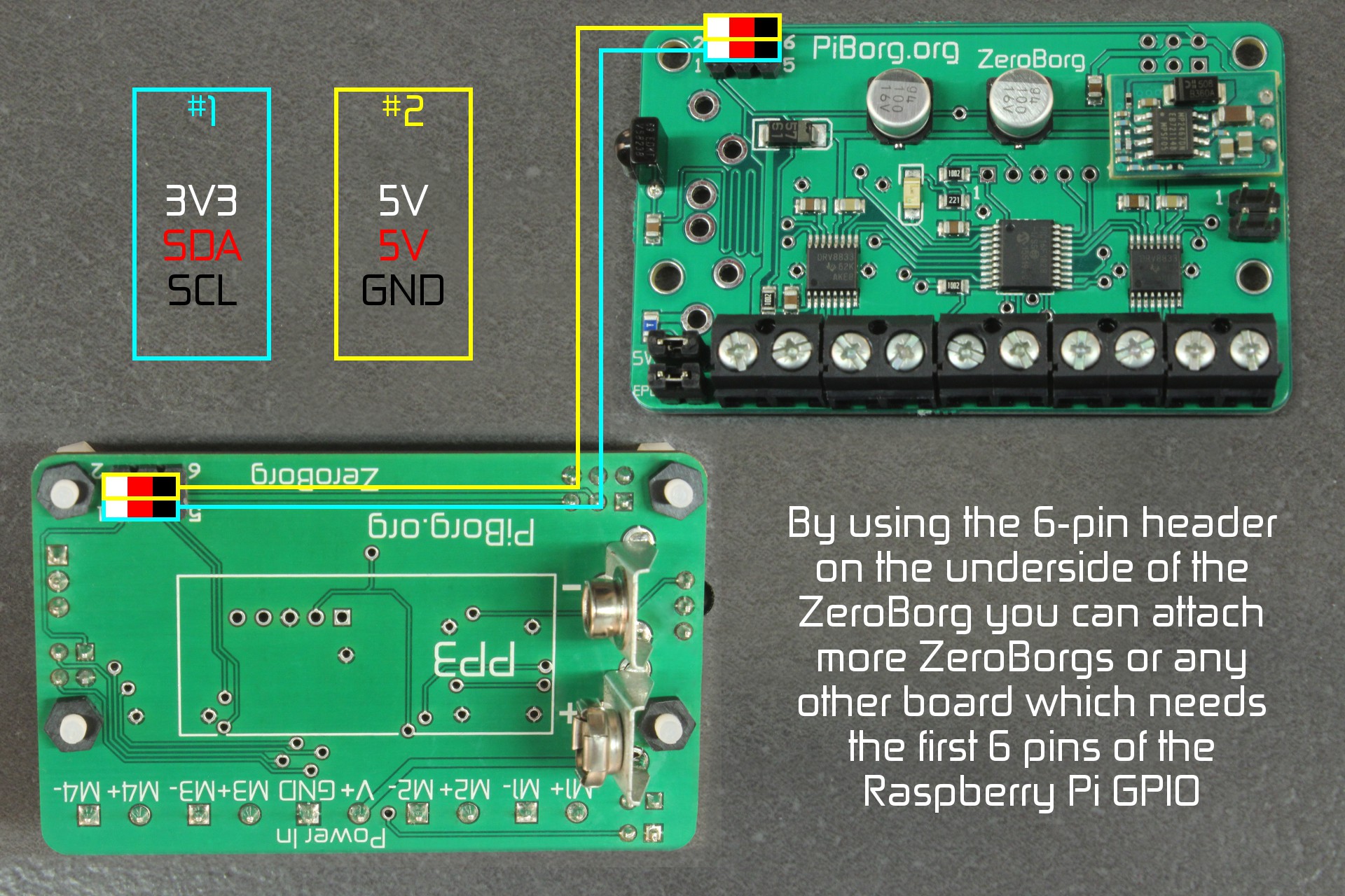
This works great with some of our other boards such as UltraBorg - for servos / ultrasonics or PicoBorg Reverse - for more powerful motors.
As you can see you may connect multiple boards at once, read further down for instructions on configuring the software correctly to run with multiple boards attached.
Connections
Power
Power can be connected in one of two ways:- Using the two pin screw terminal labelled V+ / GND
- Using the 9V connector supplied with the KS2 and KS3
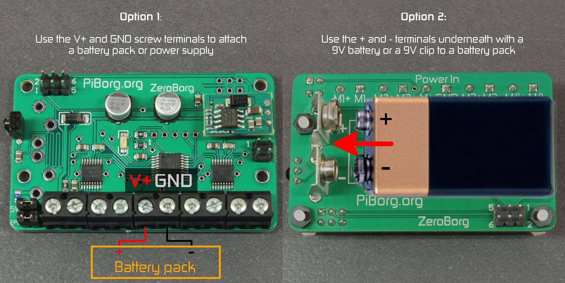
Only one of these should be used at a time!
With the KS1 power must be between 2.7 and 10.8 V.
With the KS2 and KS3 power must be between 7 and 10.8 V (for the Raspberry Pi power).
Optionally you may also connect:
- A power switch for the whole board.
This should be a toggle switch and will turn power off to the Raspberry Pi and the motors - a normally closed switch as a safety switch (emergency power off, EPO)
This allows a switch press to prevent the motors running until re-enabled by a special command,ZB.ResetEpo()
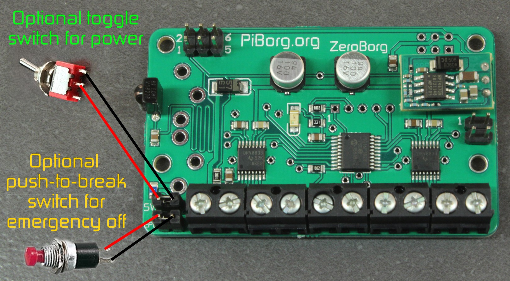
When switches are not attached the jumper should be left fitted instead.
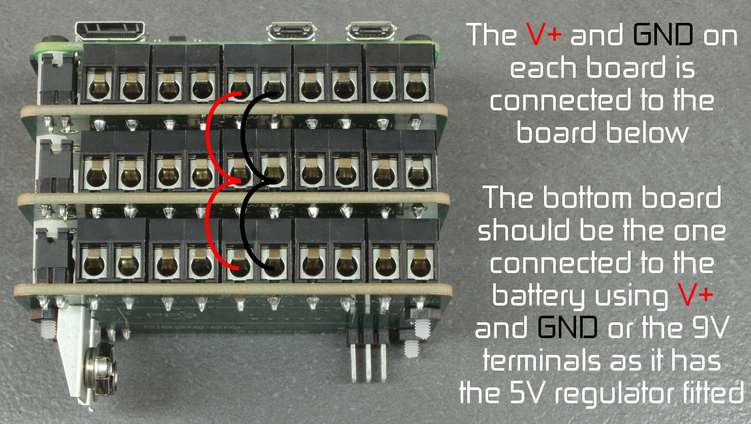
When using a stack like the KS3 you can either have separate power supplies or all share the same one by linking the power connections like this:
DC (normal) motors
You will need to add the motors (up to four) to the motor connections as shown below: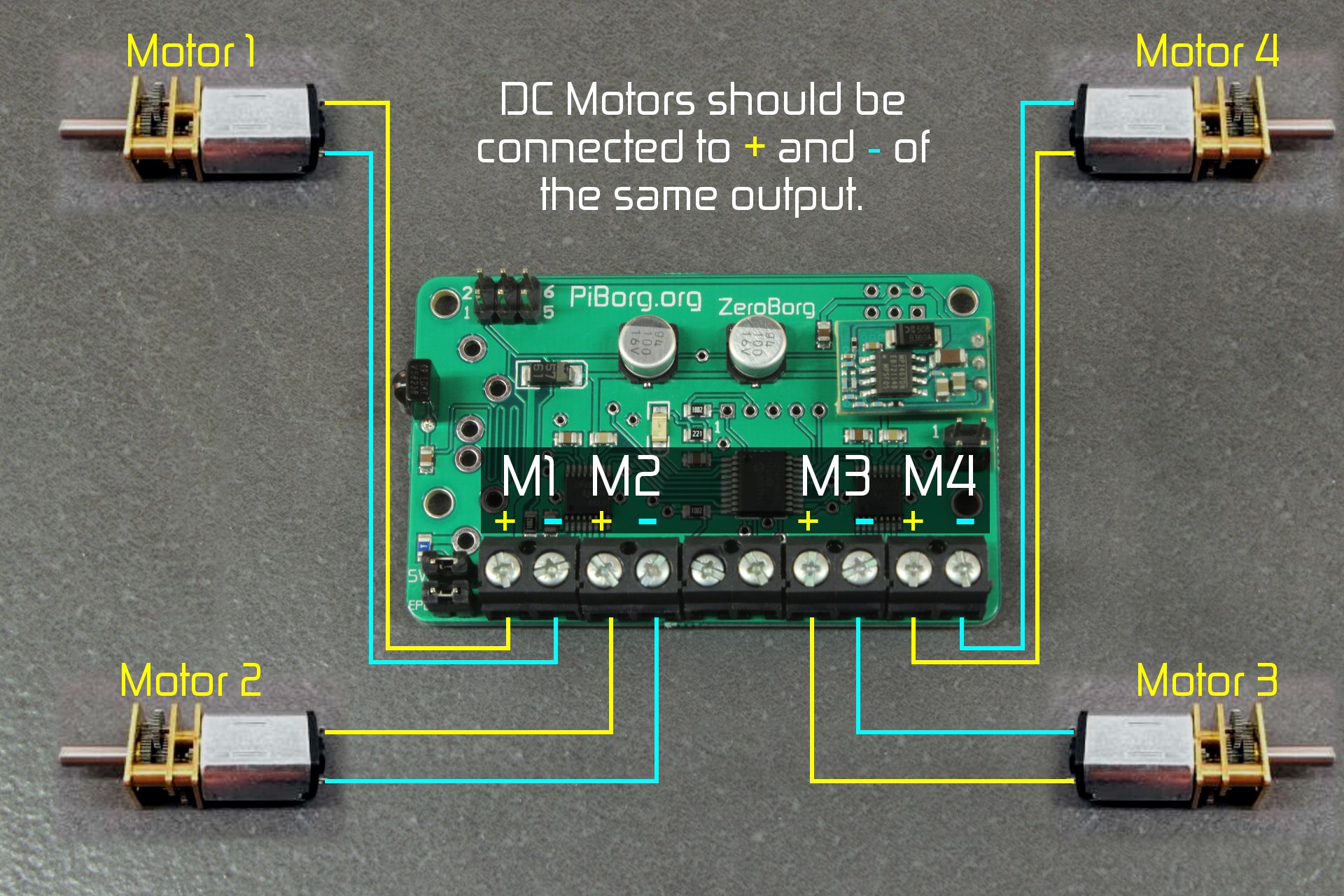
You can use any of the four outputs as desired.
If you want the standard examples to work with a two wheeled robot we recommend:
- Left motor → M1+ and M1-
- Right motor → M3+ and M3-
- Front left motor → M1+ and M1-
- Rear left motor → M1+ and M1-
- Front right motor → M3+ and M3-
- Rear right motor → M3+ and M3-
Stepper motors
You will need to add the motor(s) to either motor outputs pairs M1 / M2 or M3 / M4 as shown below: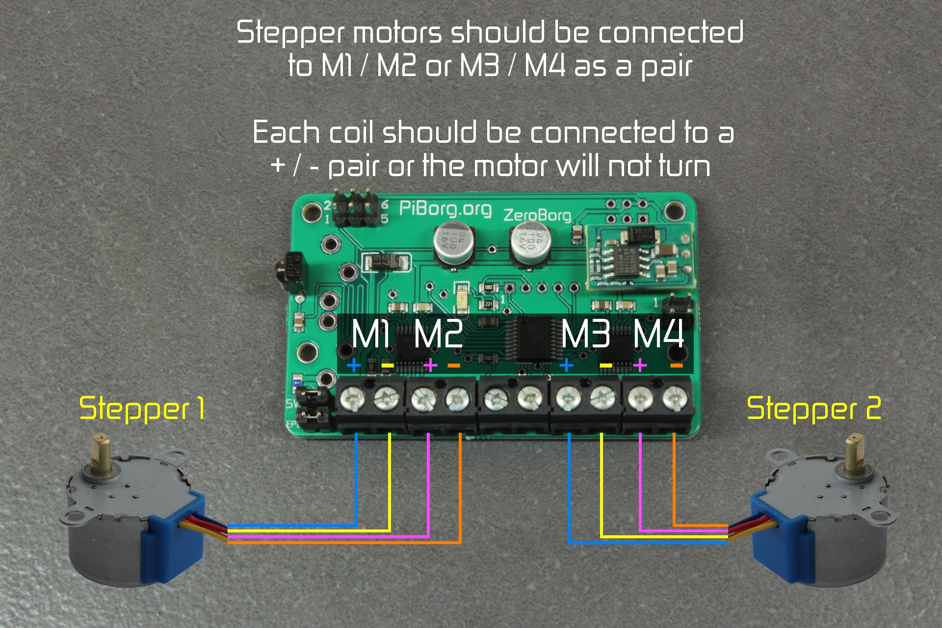
The shown stepper connection colours are based on the following internal wiring for the stepper:
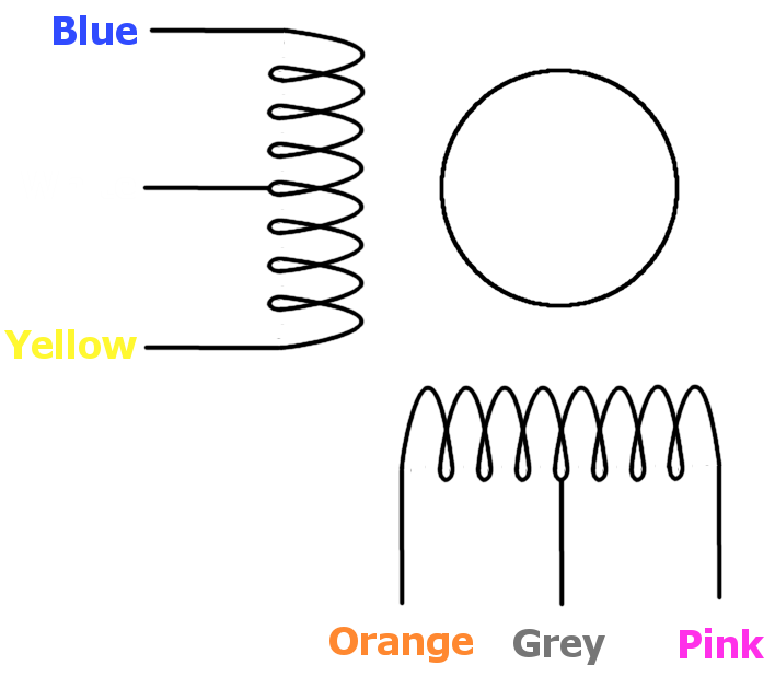
Note that on 5 / 6 wire steppers the remaining connections should be the center-taps (labelled white and grey above), these must not be connected to anything, we recommend putting some electrical tape over the end of these wires to ensure they do not contact any other connections.
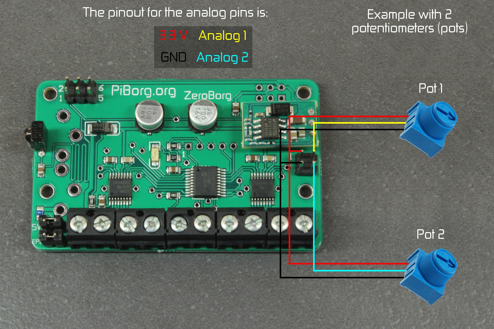
Analog inputs
There are two analog inputs on all versions of the ZeroBorg.These work between 0 and 3.3 V and can have a variety of possible uses sucha as reading potentiometers (pots) to get user input or reading temperature sensors.
The 4-pin connector provides access to the two reference outputs (0V and 3.3V) and the two analog inputs.
Infrared (IR) sensor
With the KS2 and KS3 an infrared sensor is provided.Most TV remotes should work, these have pre-configured button names in the examples:
- Sony RM-ED007 / RM-ED008 / RM-ED009
- Sony RMT-VB100L
- Samsung BN59_01015A
Other manufacturers will likely need to be configured using the
zbSaveIR.py script.Software
Please note that this installation expects you to be connected to the internet, it will download i2c-tools and python-smbus for using I²C from Python, as well as pygame for the joystick examples.On a Raspberry Pi Zero this will need a USB hub and a WiFi / Ethernet dongle.
You may need to enable I2C first, to do this:
- Enter the following command in a terminal:
sudo raspi-config - Move down to option
8 Advanced Optionsand press ENTER - Move down to option
A7 I2Cand press ENTER - Make sure
Yesis highlighted and press ENTER - When the dialog says I2C is enabled press ENTER
- Make sure
Yesis highlighted again and press ENTER - When the dialog says I2C will be loaded by default press ENTER
- Move right until
Finishis highlighted, then press ENTER
To run through the automatic installer just use this one line in a terminal:
bash <(curl https://www.piborg.org/install-zeroborg.txt)If you would prefer to manually run through the steps use the commands below:
mkdir ~/zeroborg
cd ~/zeroborg
wget http://www.piborg.org/downloads/zeroborg/examples.zip
unzip examples.zip
chmod +x install.sh
./install.sh
Manual download: http://www.piborg.org/downloads/zeroborg/examples.zip
At the end of the install a desktop icon will appear for the example GUI, you should now be ready to go.
Multiple Boards
In order to setup multiple boards there is an additional step, we need to give each board a unique address.The allowable addresses are 3 (
0x03) to 119 (0x77), the numbers in parenthesis are in hexadecimal.If you have a KS3 this will already have been done and the chosen addresses are:
0x42for the top board0x41for the middle board0x40for the bottom board (same as the default)
It also means the bottom board can be used on its own as a KS2 without changing the address.
The first task is to pick a unique number for each board, for this example we will have three boards which we will number 10, 11, and 12.
Start the Raspberry Pi with the first board
Open a terminal and start a Python prompt as follows:
cd ~/zeroborgpythonLoad the library
import ZeroBorgSet the address of the attached board, the function should tell you if this is successful or not
ZeroBorg.SetNewAddress(10)Disconnect the attached board and connect the next board, you can do this with the Raspberry Pi still running if careful, if you are worried shut the Raspberry Pi down first, then repeat the steps up to and including loading the library.
Set the address of the attached board, repeat the last two steps for each board.
ZeroBorg.SetNewAddress(11)ZeroBorg.SetNewAddress(12)Finally attach all of the boards at once, then run the following to see what addresses were found:
print ZeroBorg.ScanForZeroBorg()If everything went well the last line should show the numbers you set, e.g.
[10 11 12]You can now use them all in a script like so
# Setup the library ready for use
import ZeroBorg
# Board #1, address 10
ZB1 = ZeroBorg.ZeroBorg()
ZB1.i2cAddress = 10
ZB1.Init()
ZB1.ResetEpo()
# Board #2, address 11
ZB2 = ZeroBorg.ZeroBorg()
ZB2.i2cAddress = 11
ZB2.Init()
ZB2.ResetEpo()
# Board #3, address 12
ZB3 = ZeroBorg.ZeroBorg()
ZB3.i2cAddress = 12
ZB3.Init()
ZB3.ResetEpo()
Simply use
ZB1, ZB2, or ZB3 anywhere you would have used ZB in a single board example.You can use as many boards as there are free address numbers, over a hundred in all ^_^
General Usage
Example GUI
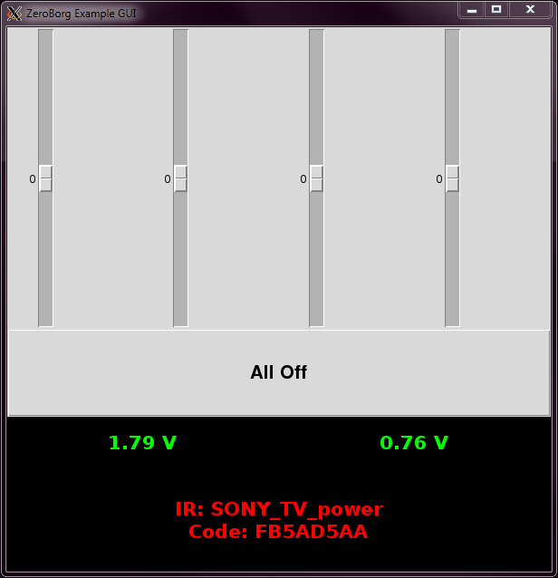
The All Off button stops all motors from moving.
The values in green are the analog voltage readings, these will be about 0 V with nothing attached.
The values in red are the latest infrared (IR) message status if fitted.
This can be run from the desktop shortcut, or from the ZeroBorg install folder (
cd ~/zeroborg) using:./zbGui.pyOther Examples
The following scripts may be run from the ZeroBorg install folder (cd ~/zeroborg):./runJoystick.sh - Uses a joystick to control two or four motors like a car (may require setup)../runMecanumJoy.sh - Uses a joystick to control four mecanum wheels like in our Kickstarter video (may require setup)../zbRemote.py - Uses a TV remote to control two or four wheels like in our Kickstarter video (may require setup)../zbStepper.py - Controls a single stepper motor, asks user for commands../zbStepperSequence.py - Controls a single stepper motor, runs a looping pattern../zbReadAnalog.py - Display the voltage readings from the analog inputs../zbReadIR.py - Display the raw codes received by the infrared sensor../zbSaveIR.py - Save new codes received by the infrared sensor for use in scripts.For more information or setup help see the full example details here.
Python Library
The example scripts make use of our Python library,ZeroBorg.py, to command the board.The library exposes all of the features of the board with the following functions:
# Setup the library ready for use
import ZeroBorg                         # Load the library
ZB = ZeroBorg.ZeroBorg()                # Create a board object
ZB.Init()                               # Setup the board
ZB.ResetEpo()                           # Reset the safety latch (optional switch)

# Setting motor speeds
ZB.SetMotor1(power)                     # Set motor 1 speed
ZB.SetMotor2(power)                     # Set motor 2 speed
ZB.SetMotor3(power)                     # Set motor 3 speed
ZB.SetMotor4(power)                     # Set motor 4 speed
ZB.SetMotors(power)                     # Set speed of all motors
ZB.MotorsOff()                          # Stop all motors

# Reading motor speeds
ZB.GetMotor1()                          # Read motor 1 speed
ZB.GetMotor2()                          # Read motor 2 speed
ZB.GetMotor3()                          # Read motor 3 speed
ZB.GetMotor4()                          # Read motor 4 speed

# Controlling the safety latch (EPO)
ZB.ResetEpo()                           # Reset the safety latch
ZB.SetEpoIgnore(state)                  # Set the safety latch to be enabled / disabled
ZB.GetEpoIgnore()                       # Read if the safety latch is enabled / disabled

# Controlling the LED
ZB.SetLed(state)                        # Turn the LED on/off
ZB.GetLed()                             # Read the LED as on/off
ZB.SetLedIr(state)                      # Makes the LED flicker when IR signals are received
ZB.GetLedIr(state)                      # Read if the LED will flicker when IR signals are received

# Reading analog inputs
ZB.GetAnalog1()                         # Read the voltage on analog pin #1
ZB.GetAnalog2()                         # Read the voltage on analog pin #2

# Reading infrared (IR) messages
ZB.HasNewIrMessage()                    # Read if a remote button has been pressed / is still pressed
ZB.GetIrMessage()                       # Read the last remote button message received

# Testing for faults
ZB.GetEpo()                             # Read the state of the safety latch

# Setting the ZeroBorg to shutdown if the RPi stops talking
ZB.SetCommsFailsafe(state)              # Set the communications timeout to enabled / disabled
ZB.GetCommsFailsafe()                   # Read if the communications timeout is enabled

# Setting parameters (before Init)
ZB.i2cAddress = address                 # Set the address of the board to use
ZB.printFunction = function             # Re-route / disable diagnostic messages

# Reading parameters (after Init)
print ZB.busNumber                      # Shows which I²C bus the board is connected on
print ZB.foundChip                      # See if the board is found / not found

# Other functions
ZeroBorg.ScanForZeroBorg()              # Sweep the I²C bus for available boards
ZeroBorg.SetNewAddress(address)         # Configure the attached board with a new address
ZB.Help()                               # Get help on the available functions
For more complete details see the ZeroBorg library reference.